3 j5 discrete control connector – Comtech EF Data KPA User Manual
Page 37
KPA Ku-Band Indoor Solid-State Power Amplifier
Revision 1
Connectors and Pinouts
MN/KPA.IOM
3–5
3.3.3
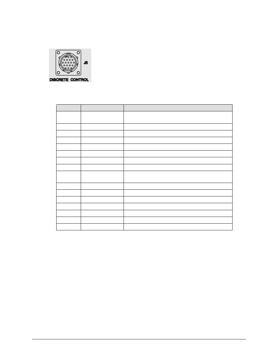
J5 DISCRETE CONTROL Connector
The J5 DISCRETE CONTROL connector is the primary input for
monitoring and controlling the ISSPA. It is a 19-pin circular connector, type
MS3112E14-19S. The pinout specification for Standalone or 1:1 Redundant
Systems is provided in Table 3-3; for 1:2 Redundant Systems, refer to
Table 3-4. See Appendix B. KPA REDUNDANT OPERATIONS for
further information about use of the KPA in 1:1 or 1:2 redundant systems.
Mating connector: ITT: KPT06J14-19P or MS3116J14-19P.
Table 3-3. J5 DISCRETE CONTROL Connector Pinout (Standalone or 1:1 Redundant Systems)
Pin #
Signal Name
Description
A
Auto Select
Momentary short to pin F to force entire subsystem to Auto
Mode.
B
BU-1 Command
Momentary short to pin F to force backup of KPA #1.
C
Priority 2 Sel
Not applicable for 1:1 system
D
BU-2 Command
Not applicable for 1:1 system
E
2 Online NO
Not applicable for 1:1 system
F
Remote Common
Control – Remote Common.
G
Online Common
Online Status Common.
H
BU Online NO
Open when Online, all other conditions tied to Pin G.
J
Manual Select
Momentary short to pin F to force entire subsystem to Manual
Mode.
K
1 Online NO
Open when Online, all other conditions tied to Pin G.
L
2 Fault NO
Not applicable for 1:1 system
M
Priority 1 SEL
Momentary short to pin F to set KPA #1 as High priority.
N
Fault Common
Fault Status Common.
P
BU Fault NO
Open when faulted, else tied to Pin N.
R
BU Offline CMD
Momentary short to pin F to force backup KPA Offline.
S
1 Fault NO
Open when faulted, else tied to Pin N.