47 fmmu (0x0600:0x06ff), Fmmu (0x0600:0x06ff), Table 78: fmmu register overview – BECKHOFF EtherCAT Registers Section II User Manual
Page 66: Table 80: register length fmmu y (0x06y4:0x06y5), 0x0600:0x06ff, Fmmu[15:0, 0x0:0x3, Logical start address, 0x4:0x5, Length
FMMU (0x0600:0x06FF)
II-54
Slave Controller
– Register Description
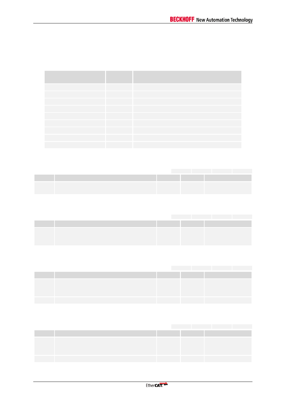
3.47 FMMU (0x0600:0x06FF)
Each FMMU entry is described in 16 Bytes from 0x0600:0x060F to 0x06F0:0x06FF. y is the FMMU
index (y=0 to 15).
Table 78: FMMU Register overview
Register Address Offset
Length
(Byte)
Description
4
2
1
1
2
1
1
1
3
Table 79: Register Logical Start address FMMU y (0x06y0:0x06y3)
ESC20
ET1100
ET1200
IP Core
Bit
Description
ECAT
PDI
Reset Value
31:0
Logical start address within the EtherCAT
Address Space.
r/w
r/-
0
Table 80: Register Length FMMU y (0x06y4:0x06y5)
ESC20
ET1100
ET1200
IP Core
Bit
Description
ECAT
PDI
Reset Value
15:0
Offset from the first logical FMMU Byte to the
last FMMU Byte + 1 (e.g., if two bytes are
used then this parameter shall contain 2)
r/w
r/-
0
Table 81: Register Start bit FMMU y in logical address space (0x06y6)
ESC20
ET1100
ET1200
IP Core
Bit
Description
ECAT
PDI
Reset Value
2:0
Logical starting bit that shall be mapped (bits
are counted from least significant bit (=0) to
most significant bit(=7)
r/w
r/-
0
7:3
Reserved, write 0
r/-
r/-
0
Table 82: Register Stop bit FMMU y in logical address space (0x06y7)
ESC20
ET1100
ET1200
IP Core
Bit
Description
ECAT
PDI
Reset Value
2:0
Last logical bit that shall be mapped (bits are
counted from least significant bit (=0) to most
significant bit(=7)
r/w
r/-
0
7:3
Reserved, write 0
r/-
r/-
0