24 gpio electrical characteristics, 25 thermal management, Table 4-2 – Artesyn MVME8100/MVME8110 Installation and Use (September 2014) User Manual
Page 92: Gpio dc electrical characteristics, Table 4-3, Gpio pull-down characteristics, Gpio electrical characteristics, Functional description
Functional Description
MVME8100 / MVME8110 Installation and Use (6806800P25G)
92
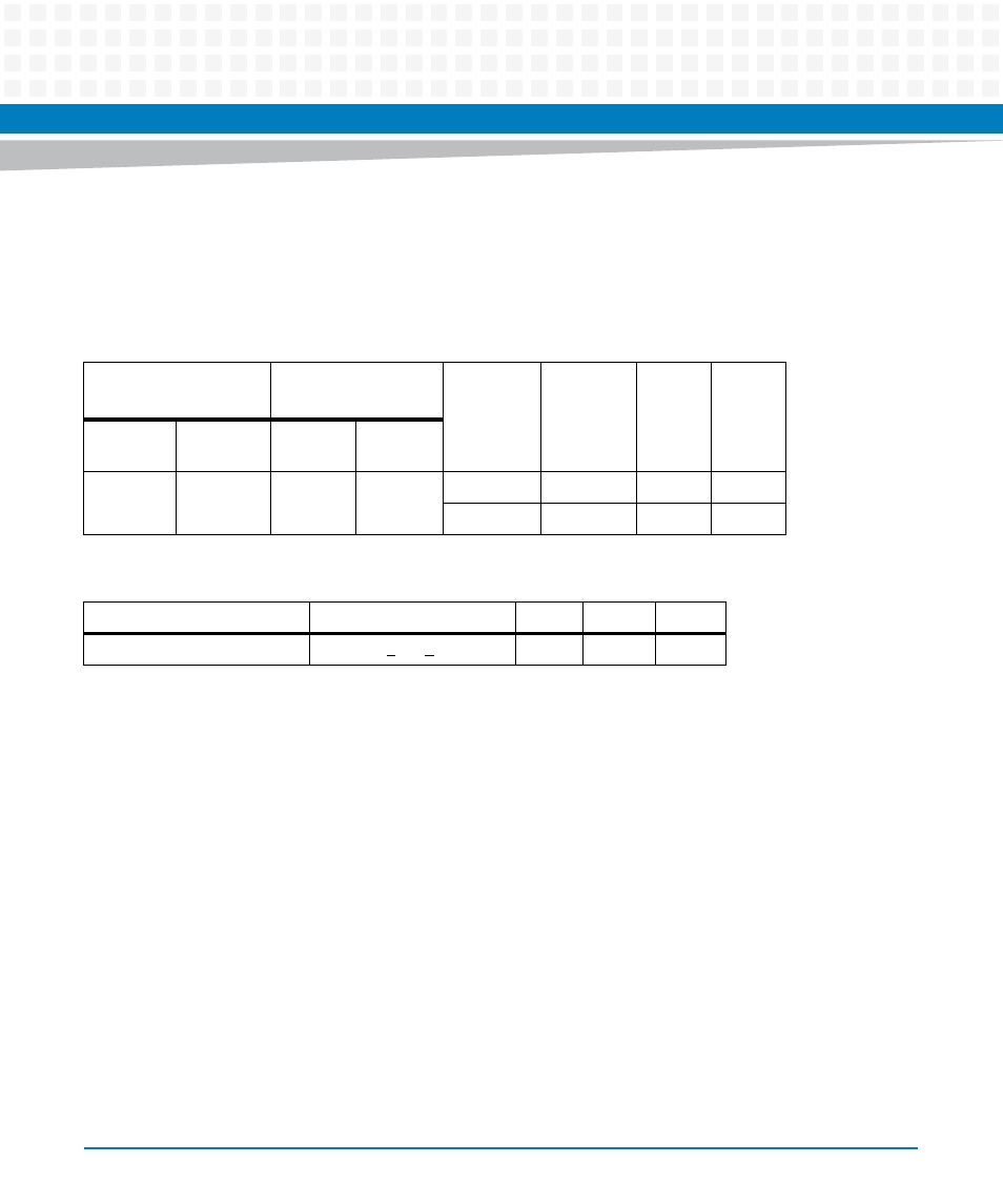
4.24 GPIO Electrical Characteristics
The four GPIO signals routed to the P0 of MVME8100 and P2 connectors have the following electrical
characteristics:
4.25 Thermal Management
The MVME8100 / MVME8110 provides three on-board temperature sensors using an ADT7461 dual
temperature sensor and a TMP112A temperature sensor. The ADT7461 internal temperature sensor
provides the temperature at the board edge on the CPU side of the board. The ADT7461 remote
temperature sensor measures the CPU temperature. The ADT7461 can measure negative temperatures
down to -64C with +/- 1C accuracy on the remote sensor and +/- 3C accuracy on the internal sensor. The
ADT7461 registers can be used to configure the low temperature limit and high temperature limit for the
local sensor as well as for the remote sensor. An interrupt can be generated if limits are exceeded. The
TMP112A temperature sensor is used to measure the temperature at the board edge opposite from the
CPU. Since the airflow direction can be different in some VME chassis, either temperature sensor can be
used to get a measure of the board inlet air temperature, depending on the air flow direction.
Table 4-2 GPIO DC Electrical Characteristics
V
IL
V
IH
Min.(V)
Max.(V)
Min.(V)
Max.(V)
V
OL
Max.(V)
V
OH
Min.(V)
I
OL
(mA)
I
OH
(mA)
-0.3
0.8
2.0
3.6
0.4
2.9
4
4
0.2
3.1
0.1
0.1
Table 4-3 GPIO Pull-Down Characteristics
Parameter
Condition
Min.
Max
Units
I/O Active Pull-down Current
V
IL
(Max) < V
IN
< V
IH
(Max)
30
150
uA