18 i2c devices, 19 reset/control cpld, 18 i2c devices 4.19 reset/control cpld – Artesyn MVME8100/MVME8110 Installation and Use (September 2014) User Manual
Page 85: Figure 4-5, I2c busses, I2c devices, Functional description
Functional Description
MVME8100 / MVME8110 Installation and Use (6806800P25G)
85
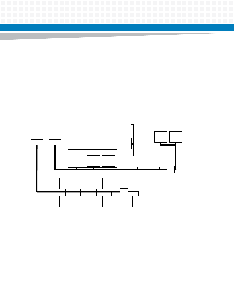
4.18 I2C Devices
The P5020 / P5010 provides four I2C controllers, but only controller 1 and controller 4 are used. The I2C
ports are connected to multiple devices such as VPD, SPD, User EEPROMs, switch configuration EEPROMs,
RTC, temperature sensors, RTM EEPROM, XMC EEPROMS, and clock devices. The RTM and XMC EEPROM
addresses are configured such that they do not have an address conflict with other on board device address.
The I2C busses and device addresses are shown in
. For more information, refer MVME8100 /
MVME8110 Programmer’s Reference.
4.19 Reset/Control CPLD
The MVME8100 / MVME8110 uses a Lattice LCMXO2280C CPLD to provide reset, power up sequencing,
timers, miscellaneous board logic, and status/control registers accessible through the P5020 / P5010 LBC
interface. The CPLD uses early 3.3V power from the +5V backplane and can be programmed through JTAG
interface pins through the JTAG connector. It uses a 1.8 MHz oscillator for logic control.
Figure 4-5
I2C Busses
CPU
FREESCALE
(U79)
I2C_1
I2C
_4
PCIE
EP
EEPROM
(U20)
SRIO
SWITCH
(U104)
RTM
VPD
EEPROM
0x
51
(local)
0x54
0x52
0x6E
0x6E
0x5D
0x74
0x57
SRIO
RC
EEPROM
(U6)
0x55
PCIE SW1
RC
EEPROM
(U3)
0x68
RTC
(U24)
0x52
0x50
I2 C
Buffer
(U127)
I2 C
Buffer
(U128)
VPD
EEPROM
(U23)
USER
EEPROM
(U45)
CLOCK
(U75)
PCIE
SWITCH
(U126)
CLOCK
(U112)
XMC1
(XJ1)
XMC 2
(XJ2)
SPD
EEPROM
(U18)
TEMP
SENSE
1
(U22)
TEMP
SENSE
2/3
(U118)
0x50
0x48
0x4C
0x50
(local)
SRIO
EP
EEPROM
(U43)
0x54
P5020 / P5010
MVME8100
(FREESCALE) P5020