Table 3-7, Vxs p0 connector (applicable to mvme8100 only), Controls, leds, and connectors – Artesyn MVME8100/MVME8110 Installation and Use (September 2014) User Manual
Page 61
Controls, LEDs, and Connectors
MVME8100 / MVME8110 Installation and Use (6806800P25G)
61
A30
PMC IO 60
B30
DATA 31
C30
PMC IO 59
D30
COM4_RTS
_N/COM4_
TX_P
Z30
GND
A31
PMC IO 62
B31
GND
C31
PMC IO 61
D31
GND
Z31
GIGE4_MD
IO3_N
A32
PMC IO 64
B32
+5V
C32
PMC IO 63
D32
+5V
Z32
GND
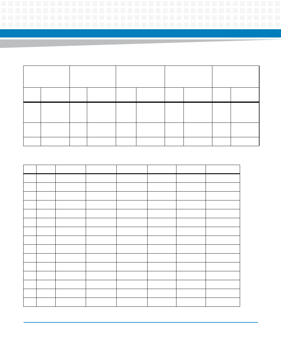
Table 3-7 VXS P0 Connector (applicable to MVME8100 only)
Pin
Row G
Row F
Row E
Row D
Row C
Row B
Row A
1
NC
GND
P1_TX0_N
P1_TX0_P
GND
P1_RX0_N
P1_RX0_P
2
GND
P1_TX1_N
P1_TX1_P
GND
P1_RX1_N
P1_RX1_P
GND
3
NC
GND
P1_TX2_N
P1_TX2_P
GND
P1_RX2_N
P1_RX2_P
4
GND
P1_TX3_N
P1_TX3_P
GND
P1_RX3_N
P1_RX3_P
GND
5
NC
GND
SG_TX0_N
SG_TX0_P
GND
SG_RX0_N
SG_RX0_P
6
GND
NC
NC
GND
NC
NC
GND
7
GPIO0
GND
NC
NC
GND
NC
NC
8
GND
NC
NC
GND
NC
NC
GND
9
GPIO1
GND
NC
NC
GND
NC
NC
10
GND
SATA_TX_N
SATA_TX_P
GND
SATA_RX_N SATA_RX_P
GND
11
NC
GND
SG_TX1_N
SG_TX1_P
GND
SG_RX1_N
SG_RX1_P
12
GND
P2_TX0_N
P2_TX0_N
GND
P2_RX0_N
P2_RX0_P
GND
13
NC
GND
P2_TX1_N
P2_TX1_P
GND
P2_RX1_N
P2_RX1_P
14
GND
P2_TX2_N
P2_TX2_P
GND
P2_RX2_N
P2_RX2_P
GND
15
NC
GND
P2_TX3_N
P2_TX3_P
GND
P2_RX3_N
P2_RX3_P
Table 3-6 P2 Connectors (continued)
P2 Connector (1st
Row)
P2 Connector (2nd
Row)
P2 Connector (3rd
Row
P2 Connector (4th
Row)
P2 Connector (5th
Row)
Pin
Name
Signal
Description
Pin
Name
Signal
Description
Pin
Name
Signal
Description
Pin
Name
Signal
Description
Pin
Name
Signal
Description