2 power requirements, Table 2-3, Operating voltages – Artesyn MVME8100/MVME8110 Installation and Use (September 2014) User Manual
Page 33: Table 2-4, Power requirements, Table, Hardware preparation and installation
Hardware Preparation and Installation
MVME8100 / MVME8110 Installation and Use (6806800P25G)
33
2.3.2
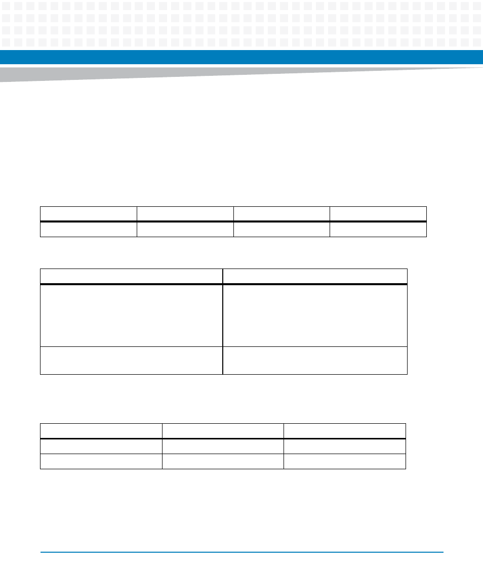
Power Requirements
The MVME8100 / MVME8110 uses the backplane +5V source to power each on board power
supply. The +3.3V backplane supply is not utilized in order to have backward compatibility with
old 3-row chassis. The -12V and +12V is routed through to the XMC and PMC connectors. The
power estimates provided in the following table is the total board consumption from +5V,
excluding the PMC/XMC, SATA HDD/SSD and USB devices.
The following table shows the power limits due to the available 5 volts pins, when the
MVME8100 is installed in either a 3-row or 5-row chassis and when PMCs/XMCs are present.
Table 2-3 Operating Voltages
Voltages
Minimum
Normal
Maximum
+5.0V
4.875V (-2.5%)
5.0V
5.25V (+5%)
Table 2-4 Power Requirements
Board Variant
Power
MVME8100-202200401S/E
MVME8110-01S/E
(ENP1)
Board idle at OS prompt: 38 Watts, typical
Operating load*: 42 Watts, typical
54 Watts, Max(@55°C)
* Operating conditions: No RTM, PMC/XMC or
peripherals.
MVME8100-202180404
(ENP4)
Operating load*: 65 Watts, max (@85°C card edge
temperature)
Chassis Type
Power Limit
Power limits PMCs or XMCs
3-Row
70 W maximum
Below 70 W
1
5-Row
90 W maximum
Below 90 W
1
1. Keep below power limit. Cooling limitations must be considered.