Table 3-14, Xmc connectors, Controls, leds, and connectors – Artesyn MVME8100/MVME8110 Installation and Use (September 2014) User Manual
Page 69: Table 3-14 xmc connectors
Controls, LEDs, and Connectors
MVME8100 / MVME8110 Installation and Use (6806800P25G)
69
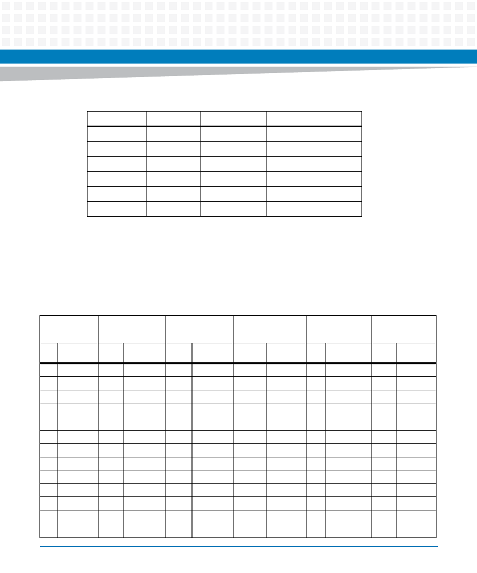
XMC Connector
MVME8100 / MVME8110 supports two XMC sites. The board only supports J15 for XMC site 1
and J25 for XMC site 2.
9
TDI
10
GND
11
No Pin Key
12
Reserved - NC
13
GND
14
Reserved - NC
15
GND
16
Reserved - NC
17
GND
18
Reserved - NC
19
GND
20
Reserved - NC
Table 3-13 Asset JTAG Header Pin Assignment (continued)
PIN Number
Description
PIN Number
Description
Table 3-14 XMC Connectors
XJ1/2 (ROW A) XJ1/2 (ROW B)
XJ1/2 (ROW C)
XJ1/2 (ROW D)
XJ1/2 (ROW E)
XJ1/2 (ROW F)
Pin
No
Signal
Description
Pin
No
Signal
Description
Pin No
Signal
Description
Pin No
Signal
Description
Pin
No
Signal
Description
Pin
No
Signal
Description
1
RX0 +
1
RX0 -
1
+3.3V
1
RX0 +
1
RX1 -
1
+3.3V
2
GND
2
GND
2
JTAG TRST
2
GND
2
GND
2
HRESET
3
NC
3
NC
3
+3.3V
3
NC
3
NC
3
+3.3V
4
GND
4
GND
4
JTAG TCK
4
GND
4
GND
4
MRSTO
(PULLED
UP)
5
NC
5
NC
5
+3.3V
5
NC
5
NC
5
+3.3V
6
GND
6
GND
6
JTAG TMS
6
GND
6
GND
6
+12V
7
NC
7
NC
7
+3.3V
7
NC
7
NC
7
+3.3V
8
GND
8
GND
8
JTAG TMS
8
GND
8
GND
8
-12V
9
NC
9
NC
9
NC
9
NC
9
NC
9
+3.3V
10
GND
10
GND
10
JTAG TDO
10
GND
10
GND
10
GA 0
11
TX0
11
TX0 -
11
BIST
(PULLED
UP)
11
TX1 +
11
TX1 -
11
+3.3V