Altera MAX 10 Embedded Memory User Manual
Page 26
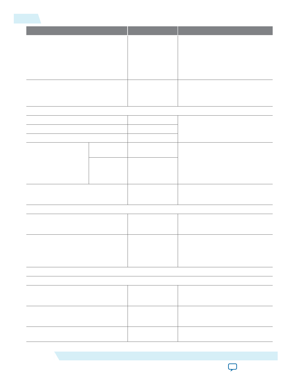
Parameter
Values
Description
How wide should the 'q' output bus be?
1, 2, 3, 4, 5, 6, 7, 8, 9,
10, 11, 12, 13, 14, 15,
16, 17, 18, 19, 20, 21,
22, 23, 24, 25, 26, 27,
28, 29, 30, 31, 32, 36,
40, 48, 64, 72, 108,
128, 144, and 256.
Specifies the width of the 'q' output bus
in bits.
How many
32, 64, 128, 256, 512,
1024, 2048, 4096,
8192, 16384, 32768,
and 65536.
Specifies the number of
words.
What should the memory block type be?
Auto
On/Off
Specifies the memory block type. The
types of memory block that are
available for selection depends on your
target device.
M9K
On/Off
LC
On/Off
Options
Use default
logic cell style
On/Off
Specifies the logic cell implementation
options. This option is enabled only
when you choose LCs memory type.
Use Stratix
M512
emulation logic
cell style
On/Off
Set the maximum block depth to
Auto, 32, 64, 128,
256, 512, 1024, 2048,
4096, and 8192
Specifies the maximum block depth in
words. This option is disabled only
when you choose LCs memory type.
What clocking method would you like to use?
Single clock
On/Off
A single clock and a clock enable
controls all registers of the memory
block.
Dual clock: use separate ‘input’ and
‘output’ clocks
On/Off
An input and an output clock controls
all registers related to the data input
and output to/from the memory block
including data, address, byte enables,
read enables, and write enables.
Parameter Settings: Regs/Clkens/Byte Enable/Aclrs
Which ports should be registered?
'data' and 'wren' input ports
—
This option is automatically enabled.
Specifies whether to register the read
or write input and output ports.
'address' input port
—
This option is automatically enabled.
Specifies whether to register the read
or write input and output ports.
'q' output port
On/Off
Specifies whether to register the read
or write input and output ports.
4-4
RAM: 1-Port IP Core Parameters For MAX 10 Devices
UG-M10MEMORY
2015.05.04
Altera Corporation
RAM: 1-Port IP Core References