Connect the relay output, Mount the es7510, Connect the ethernet ports – Comtrol ES7510 User Manual
Page 11
RocketLinx ES7510 User Guide: 2000544 Rev. B
Connect the Relay Output - 11
Hardware Installation
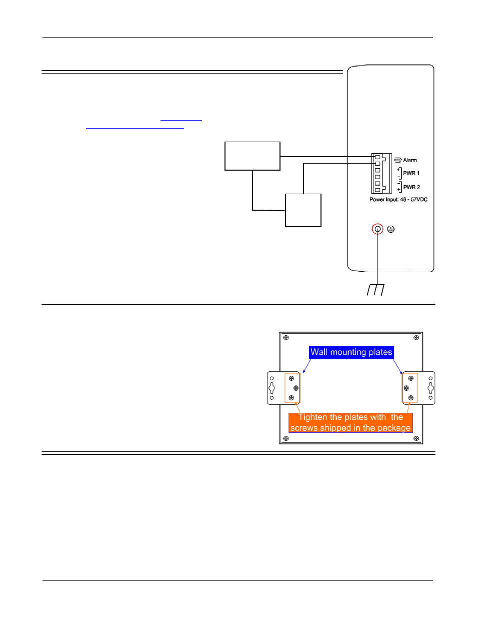
Connect the Relay Output
If desired, connect the Relay Output (DO). The
relay contacts are energized, (open) for normal
operation and close for fault conditions that can
be defined using the ES7510 web user interface
or Command Line Interface. See
131 for information about configuring events.
The events include:
•
Dry output
•
Port link failure
•
Ping failure
•
Ping reset
•
Ring failure
Note: The relay contact only supports 1A current
at 24VDC. Do not apply voltage and
current that exceeds these specifications.
Mount the ES7510
You can use the following procedure to mount the ES7510 on the wall.
Attach the brackets to the ES7510 by using the screws
provided in the plate mounting kit.
•
To avoid damage to the ES7510 circuitry, make sure that
you use the screws included in the plate mounting
package to attach and tighten the wall-mount plates
onto the ES7510. The screws are M3 and are 6 mm in
length.
•
The ES7510 will disperse heat through the metal case
during PoE port operation. The ES7510 should be
installed and mounted onto a panel that provides good
heat dispersion.
Connect the Ethernet Ports
You can use the following information to connect standard Ethernet cables between the ES7510 Ethernet
ports and the network nodes.
•
Ports 1-8 are Fast Ethernet (10/100BASE-TX) PoE ports that are IEEE 802.3af (PoE) and IEEE 802.3at
(PoE Plus) compliant.
•
Ports 9-10 are Gigabit (10/100/1000BASE-TX) ports.
Maximum Relay
Current
Extra Alarm
Power Source
Alert
Device