4 - 6 -1. t r ansmitter offsets, 6-5. specifications – Kenwood TM-741A User Manual
Page 76
Attention! The text in this document has been recognized automatically. To view the original document, you can use the "Original mode".
4-2-7. Attenuator ON/OFF
(With the UT-28S/50S)
See page 25.
4-2-8. ALT (Automatic Lock Tuning)
(With the UT-1200)
See page 26.
4-3-4. Bandwidth Selection
(With the UT-28S)
See page 28.
4-4-2. Microprocessor Initialization
band
28MHz
50MHz
1200MHz
VFO, Call and
Memory channel 1
frequency
29.000
MHz
51.000
MHz
1240.000
MHz
Frequency step
lOkHz
lOkHz
25kHz
Tone frequency
88.5Hz
88.5Hz
88.5Hz
4-1-1. MHz key (With the UT-28S except
U.S.A. and Canada)
The chart below illustrates the way the displayed
frequency will change when you increase or decrease the
operating frequency in 1 MHz increment.
For ex. 29.6-^28.!•«—(decrease) 29.1 (increase)^28.0
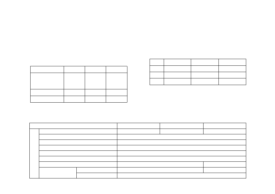
4 - 6 -1.
T r ansmitter Offsets
28MHz band
50MHz band
1200MHz band
-I-
+ lOOkHz
+ lMHz
12MHz
-
- lOOkHz
-IMHz
-12MHz
—
-
-
- 20MHz
7-6-5. Specifications
UT-28S
UT-50S
UT-1200
G
E
N
E
R
A
L
Frequency range
28 ~ 29.7
50~54
1240 ~ 1300
Mode
F3(FM)
Antenna impedance
son
Operating tenperature
-20°C~+60°C
Power requirements
DC13.8V ± 15%(11.7~15.8V)
Ground
Negative
Frequency stability
Less than ±10ppM
Less than ±3ppM
Current drain
Transmit mode
Less than 11.5A
Less than 6.5A
Receiver mode
^ Less than 1.2A
76