1-4. rear panel and side case – Kenwood TM-741A User Manual
Page 20
Attention! The text in this document has been recognized automatically. To view the original document, you can use the "Original mode".
4-1-4. Rear Panel and Side Case
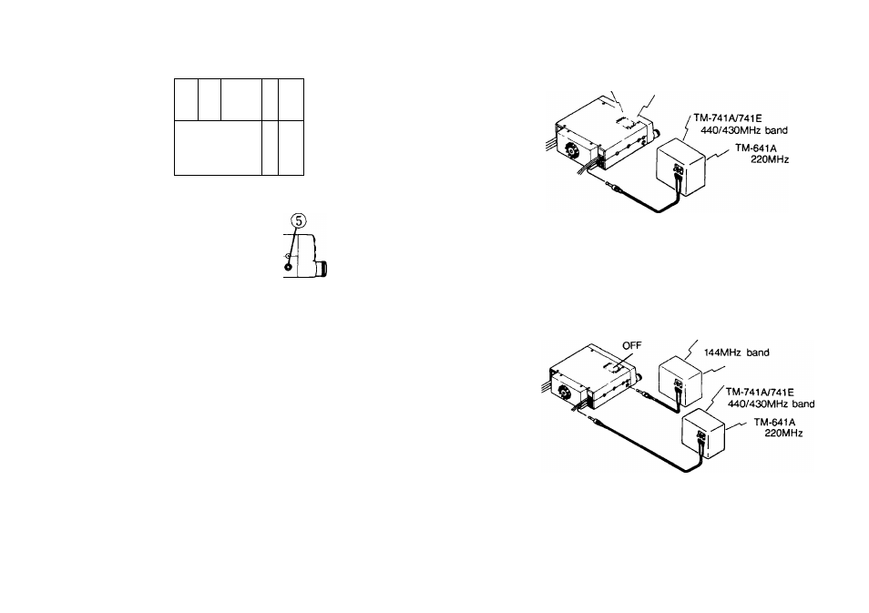
Example
144MHz.
TM-741A/741E-
440/430MHZ
TM-641A
220MHz
P
J
■ 144MHz
■TM-741A/741E
440/430MHZ
TM-641A
220MHz
144MHz band
w
(DANTENNA connector
Attach an antenna with a low SWR and impedance of 50
ohms.
(2) 13.8 VDC power input connector
Connect the supplied DC power cable to this connector.
Pay close attention to the polarity. Red is positive and
black is negative.
(DFuse holder
Contains a 15A fuse. Do not use a larger fuse as
damage might result to the transceiver.
(3) External speaker jack (Rear panel)
The speaker should have an impedance of 8 ohms.
The audio is switched to the external speaker (no sound
is output from the built-in transceiver speaker).
(5)External speaker jack (Side case)
The speaker should have an impedance of 8 ohms.
The audio is switched from the built-in transceiver
speaker to the external speaker (no sound is output from
the built-in transceiver speaker).
Example
We recommend the use of the optional external speaker
SP-50B.
20