Benchmark 1.5ln low nox boiler, Gf-120, Figure 7-4: burner assembly exploded view – AERCO BMK 1.5 LN July 2011 User Manual
Page 79
CHAPTER 7: MAINTENANCE
PR2: 05/09/12 Page
79 of 152
Benchmark 1.5LN Low NOx Boiler
Operation and Maintenance Manual
OMM-0041_0D
GF-120
AERCO International, Inc. • 100 Oritani Dr. • Blauvelt, NY 10913 • Ph: 800-526-0288
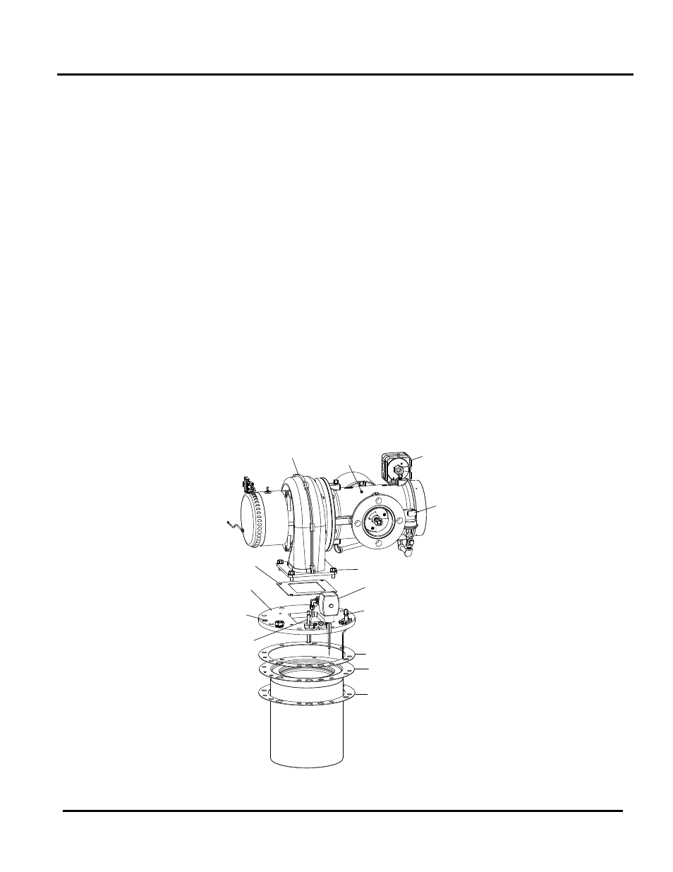
14. Remove the four (4) 5/16-18 hex head screws securing the blower to the burner plate
(Figure 7-5).
15. Remove the blower and air/fuel valve from the burner plate by lifting straight up. Also,
remove the blower gasket.
16. Remove the eight (8) 3/8-16 nuts from the burner flange (Figure 7-4) using a 9/16” wrench.
NOTE
The burner assembly is heavy, weighing approximately
25 pounds.
17. Remove the burner assembly from burner flange by pulling straight up.
18. Remove and replace the two (2) burner gaskets.
NOTE
During reassembly, apply high-temperature, anti-seize
lubricant to the threads of the igniter-injector and
grounding screw. Also, ensure that the igniter-injector is
properly positioned as indicated in Figure 7-3. Torque the
igniter-injector to 15 ft-lbs.
19. Beginning with the burner assembly removed in step 17, reinstall all the components in the
reverse order that they were removed.
20. Ensure that the igniter-injector and flame detector cutouts in the burner plate are properly
aligned with the heat exchanger top flange.
AIR/FUEL
VALVE
BLOWER
IGNITOR-
INJECTOR
FLAME
DETECTOR
STAGED IGNITION
ASSEMBLY
BURNER GASKET
BURNER GASKET
BURNER
HEX HEAD SCREWS (4)
BLOWER
GASKET
BURNER
PLATE
BLOWER
PROOF
SWITCH
BLOCKED
INLET
SWITCH
GROUNDING
SCREW
Figure 7-4: Burner Assembly Exploded View