10 start/stop levels, Benchmark 1.5ln low nox boiler, Gf-120 – AERCO BMK 1.5 LN July 2011 User Manual
Page 41
CHAPTER 3: CONTROL PANEL OPERATION
PR2: 05/09/12 Page
41 of 152
Benchmark 1.5LN Low NOx Boiler
Operation and Maintenance Manual
OMM-0041_0D
GF-120
AERCO International, Inc. • 100 Oritani Dr. • Blauvelt, NY 10913 • Ph: 800-526-0288
25
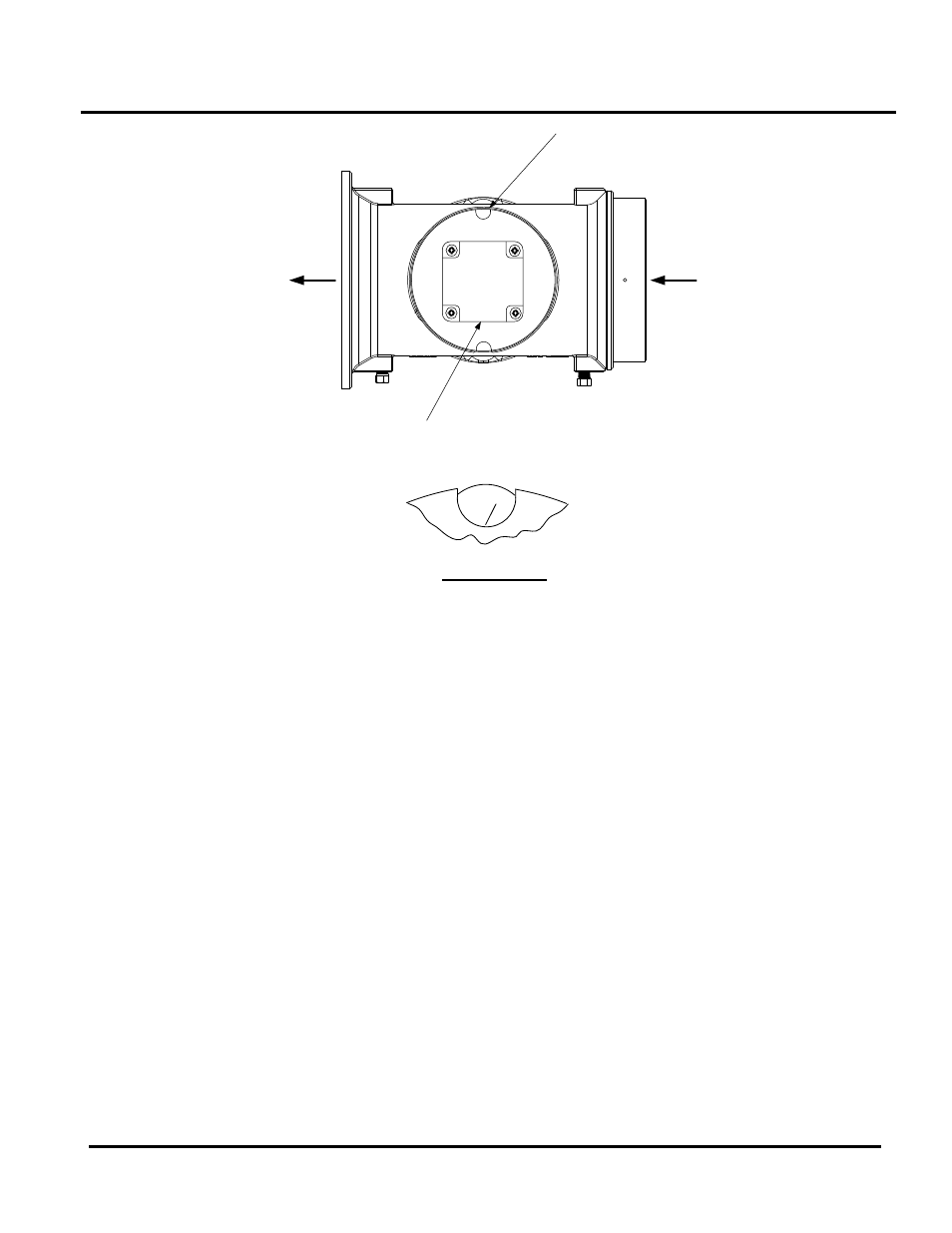
TO BLOWER
AIR IN
DIAL
(DETAIL “A”)
STEPPER
MOTOR
DETAIL “A”
Figure 3-6: Air/Fuel Valve In Ignition Position
6. Up to 7 seconds will be allowed for ignition to be detected. The igniter relay will be turned
off one second after flame is detected.
7. After 2 seconds of continuous flame, Flame Proven
will be displayed and the flame strength
will be indicated. After 5 seconds, the current date and time will be displayed in place of the
flame strength.
8. With the unit firing properly, it will be controlled by the temperature controller circuitry. The
boiler’s
VALVE POSITION will be continuously displayed on the front panel bargraph.
Once the demand for heat has been satisfied, the Control Box will turn off the dual SSOV gas
valves. The blower relay will be deactivated and the Air/Fuel Valve will be closed. Standby will
be displayed.
3.10 START/STOP LEVELS
The start and stop levels are the Air/Fuel Valve positions (% open) that start and stop the unit,
based on load. These levels are Factory preset as follows:
Start Level: 20%
Stop Level: 16%
Normally, these settings should not require adjustment.
Note that the energy input of the boiler is not linearly related to the Air/Fuel Valve position. Refer
to Table 3-7 for the relationship between the energy input and Air/Fuel Valve position for a unit
running on natural gas.