Chapter 4, 1 required tools & instrumentation, 2 installing gas supply manometer – AERCO BMK 1.5 LN July 2011 User Manual
Page 44: Benchmark 1.5ln low nox boiler, Gf-120
CHAPTER 4: INITIAL START-UP
Page
44 of 152 PR2: 05/09/12
Benchmark 1.5LN Low NOx Boiler
Operation and Maintenance Manual
OMM-0041_0D
GF-120
AERCO International, Inc. • 100 Oritani Dr. • Blauvelt, NY 10913 • Ph: 800-526-0288
4.2.1
Required Tools & Instrumentation
The following tools and instrumentation are necessary to perform combustion calibration of the
unit:
•
Digital Combustion Analyzer: Oxygen accuracy to ± 0.4%; Carbon Monoxide (CO) and
Nitrogen Oxide (NOx) resolution to 1PPM.
•
16 inch W.C. manometer or equivalent gauge and plastic tubing.
•
1/4" NPT-to-barbed fittings for use with gas supply manometer or gauge.
•
Small and large flat blade screwdrivers.
•
Tube of silicone adhesive
4.2.2
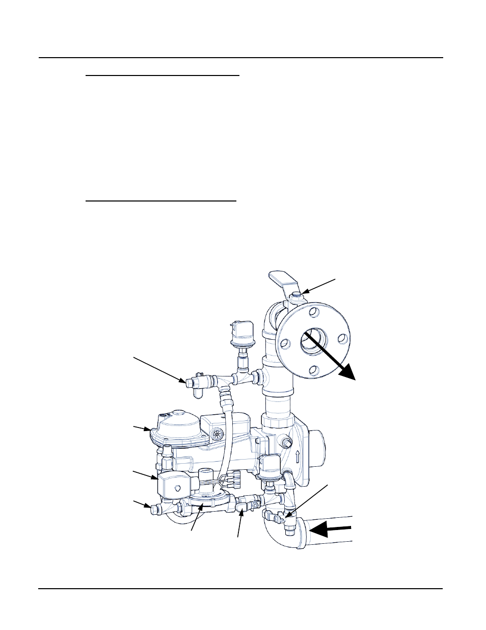
Installing Gas Supply Manometer
The gas supply manometer (or gauge) is used to calibrate the gas pressure to be monitored on
the downstream side of the SSOV during the Combustion Calibration procedures described in
paragraph 4.4.
The gas supply manometer is installed at the downstream location on the 1/4” NPT port shown
in Figure 4-1. Note that a 1/4” plug must be removed from the port in order to install the
manometer.
Figure 4-1: Combustion Calibration & RSI Manometer Installation Locations
TO
AIR/FUEL
VALVE
GAS INLET
SSO
RSI
SOLENOID
VALVE
RSI BLEED-
OFF VALVE
1/4” NPT PLUG
(INSTALL
MONOMETER HERE
FOR RSI PRESSURE
TEST/CALIBRATION)
MANUAL SHUT-
OFF VALVE
RSI
PRESSURE
REGULATOR
RSI GAS
VALVE
1/4” NPT PLUG
(INSTALL
MONOMETER HERE
FOR COMBUSTION
CALIBRATION)