Appendix c. configuration information, Aerco/protonode gateway, Gf-129 – AERCO ProtoNode Gateway Rev 1 (with internal LEDs) User Manual
Page 33
Page 33 of 64
USER MANUAL
AERCO/ProtoNode Gateway
OMM-0080_0D
AERCO International, Inc.
• 100 Oritani Dr. • Blauvelt, New York 10913 • Phone: 800-526-0288
VD2:011712
1
GF-129
Appendix C. CONFIGURATION INFORMATION
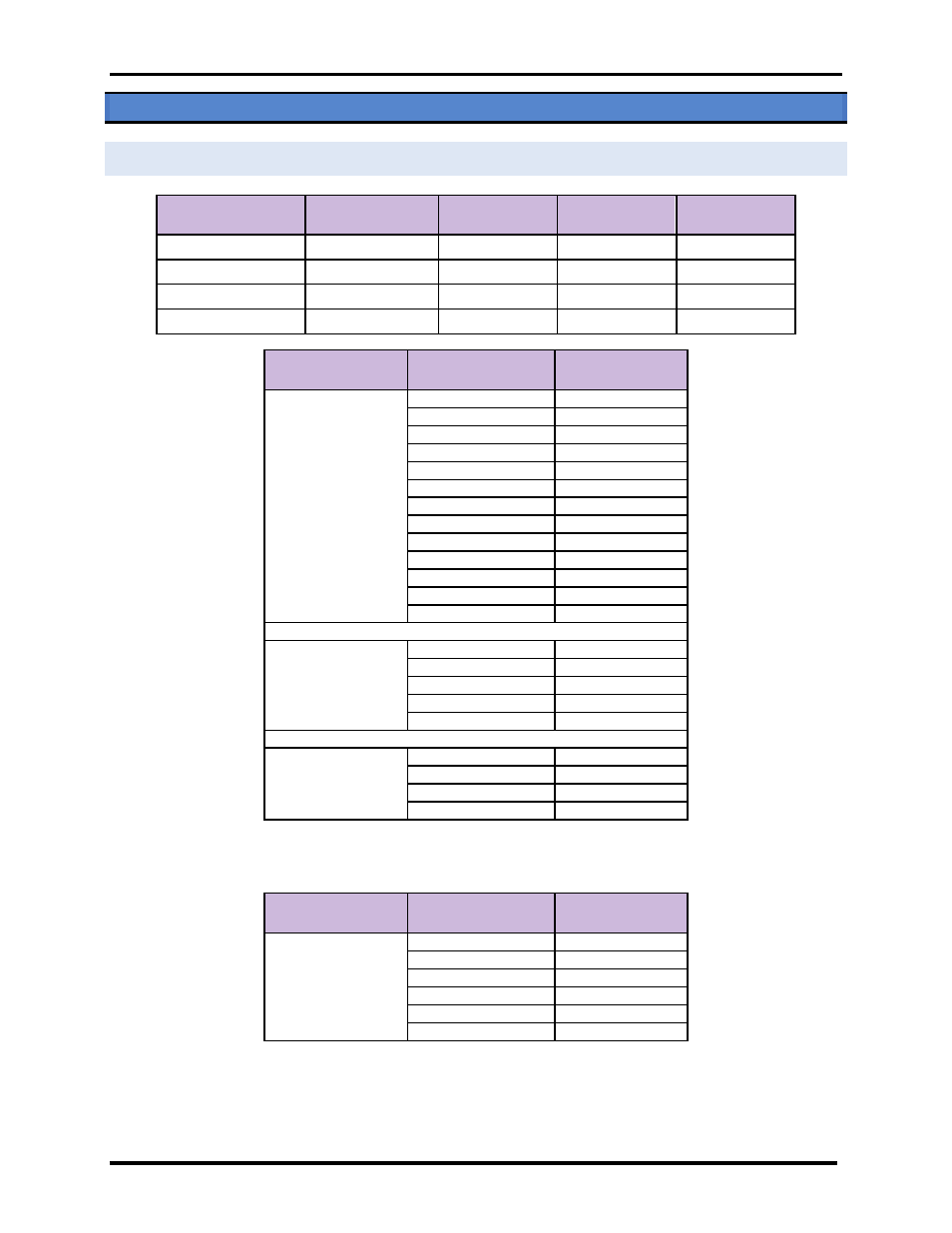
C.1 Default Modbus RTU COM Settings for AERCO Controllers
Serial Port Setting
ACS, BMS II, BMS
ECS/SP
BCM
(Modulex)
C-More
Baud Rate
≤19200
≤38.4
9600
9600
Data Bits
8
8
8
8
Stop Bits
1
1
1
1
Parity
None
None
None
None
Configuration
Controllers
Modbus Default
Address
12
C-More
Controllers
&
1 ACS/BMS II/BMS
C-more 1
1
C-more 2
2
C-more 3
3
C-more 4
4
C-more 5
5
C-more 6
6
C-more 7
7
C-more 8
8
C-more 9
9
C-more 10
10
C-more 11
11
C-more 12
12
ACS /BMS II/BMS
128
4
Modulex
Controllers
&
1 ACS/BMS II
Modulex 1
1
Modulex 2
2
Modulex 3
3
Modulex 4
4
ACS /BMS II/BMS
128
4
ECS/SP
ECS 1
29
ECS 2
30
ECS 3
31
ECS 4
32
For Profiles defined in Section C.2.6, the ECS/SP Modbus default point addresses are defined below.
Configuration
Controllers
Modbus Default
Address
6
ECS/SP
ECS 1
17
ECS 2
18
ECS 3
19
ECS 4
20
ECS 5
21
ECS 6
22