Appendix a. troubleshooting tips, Aerco/protonode gateway, Gf-129 – AERCO ProtoNode Gateway Rev 1 (with internal LEDs) User Manual
Page 20
Page 20 of 64
USER MANUAL
AERCO/ProtoNode Gateway
OMM-0080_0D
AERCO International, Inc.
• 100 Oritani Dr. • Blauvelt, New York 10913 • Phone: 800-526-0288
VD2:011712
1
GF-129
Appendix A. TROUBLESHOOTING TIPS
A.1 - LED Diagnostics for Modbus RTU Communications Between the Protonode and AERCO’s Boiler
Controllers
The AERCO/ProtoNode Gateway units feature status LEDs that indicate a number of possible activities. The
ollowing shows how to open the unit and interpret the activity of the indication LEDs.
The lid on top of the AERCO/ProtoNode Gateway must be removed in order to see the LED’s. Pull on the lid while
holding onto the 6 pin Phoenix connector.
IMPORTANT!
Do not hold the wall mount tabs when removing the cover as these are
designed to break off if not required!
LED locations and function descriptions for LER and RER versions are shown in the following two subsections.
A.1.1 - ProtoNode LER - LED Locations and Functions
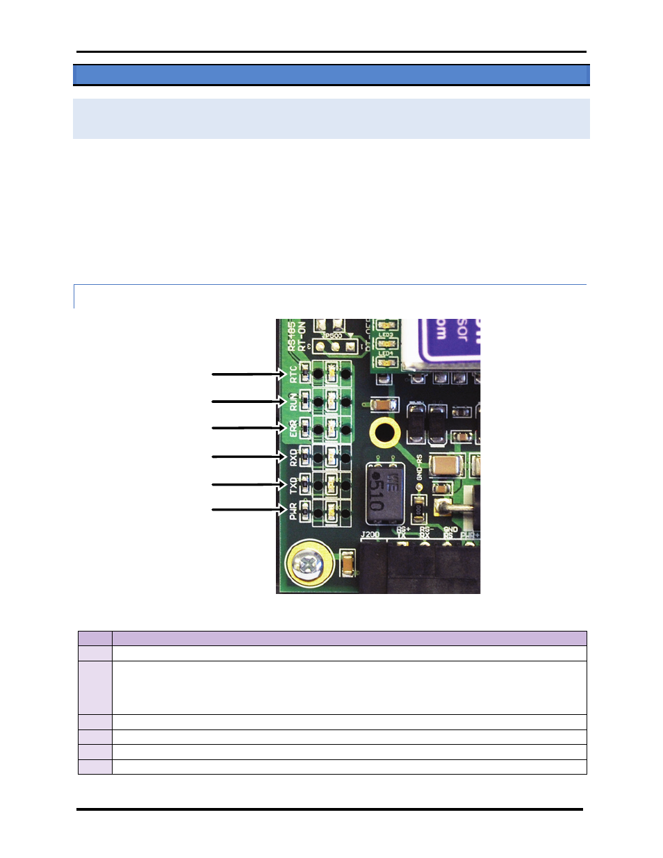
Figure 14. AERCO/ProtoNode Gateway LER Main Board Indication LED Locations
LED
DESCRIPTION
RUN
The RUN LED will start flashing 20 seconds after power up, indicating normal operation.
ERR
The SYS ERR LED will go on solid 15 seconds after power up. It will turn off after 5 seconds. A steady red
light will indicate there is a system error on the ProtoNode LER. If this occurs, immediately report the
related “system error” shown in the error screen of the RUI interface to AERCO International for
evaluation.
RX
The RX LED will flash when a message is received on the socket port.
TX
The TX LED will flash when a message is sent on the socket port.
PWR
This is the power light and should show steady green at all times when the ProtoNode LER is powered.
RTC
Unused
PWR
TX
RX
ERR
RUN
RTC