5 c-more, Aerco/protonode gateway, Gf-129 – AERCO ProtoNode Gateway Rev 1 (with internal LEDs) User Manual
Page 14
Page 14 of 64
USER MANUAL
AERCO/ProtoNode Gateway
OMM-0080_0D
AERCO International, Inc.
• 100 Oritani Dr. • Blauvelt, New York 10913 • Phone: 800-526-0288
VD2:011712
1
GF-129
.5 C-MORE
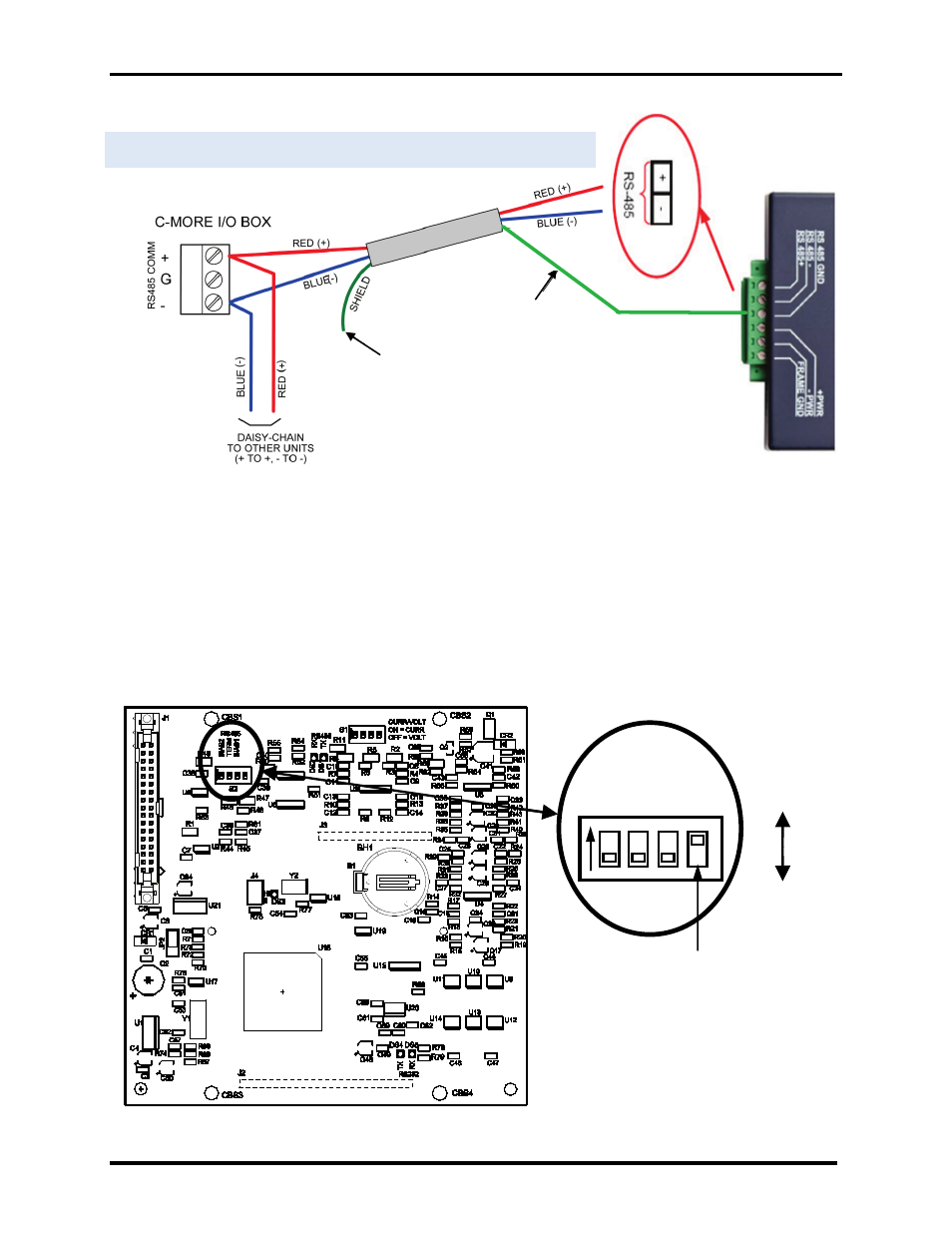
Figure 8a. RS-485 Connection to C-MORE (RS-485)
IMPORTANT NOTE
The 4-position RS485 DIP Switch (S2) on the PMC PCB of the C-More Controller must be set as
follows:
1) The termination (TERM) and bias (BIAS1 & BIAS2) DIP Switches of S2 must be set to DISABLE.
2) If an Oxygen Sensor is connected to the C-More Controller, switch R1 (see below) should be set
to DISABLED (down). If an Oxygen Sensor is NOT connected to the C-More Controller, it should
be set to ENABLED (up). Improper setting of R1 may result in error messages.
Instructions for accessing the PMC PCB and this DIP Switch can be found in Section 4.3 of ModBus
manual GF-114.
C-More Controller PMC PCB
If an Oxygen Sensor is attached to the C-
More Controller, set R1 to DISABLED
(down). If an Oxygen Sensor is NOT used,
set R1 to ENABLED (up). Factory default
setting is ENABLED.
ENABLE
DISABLE
BI
AS
2
T
ERM
BI
AS1
R1
S2
RS485
TERMINATE SHIELD
TO SIGNAL GROUND
TIE TOGETHER WITH
SHIELDS OF OTHER
UNITS AND
FLOAT AT END OF
LINE (INSULATE)
TERMINATE SHIELD
TO SIGNAL GROUND
R1