Parameters, see "measurement area details – KEYENCE LJ-V7000 Series User Manual
Page 83
83
LJ-V7000_COM_RM_E
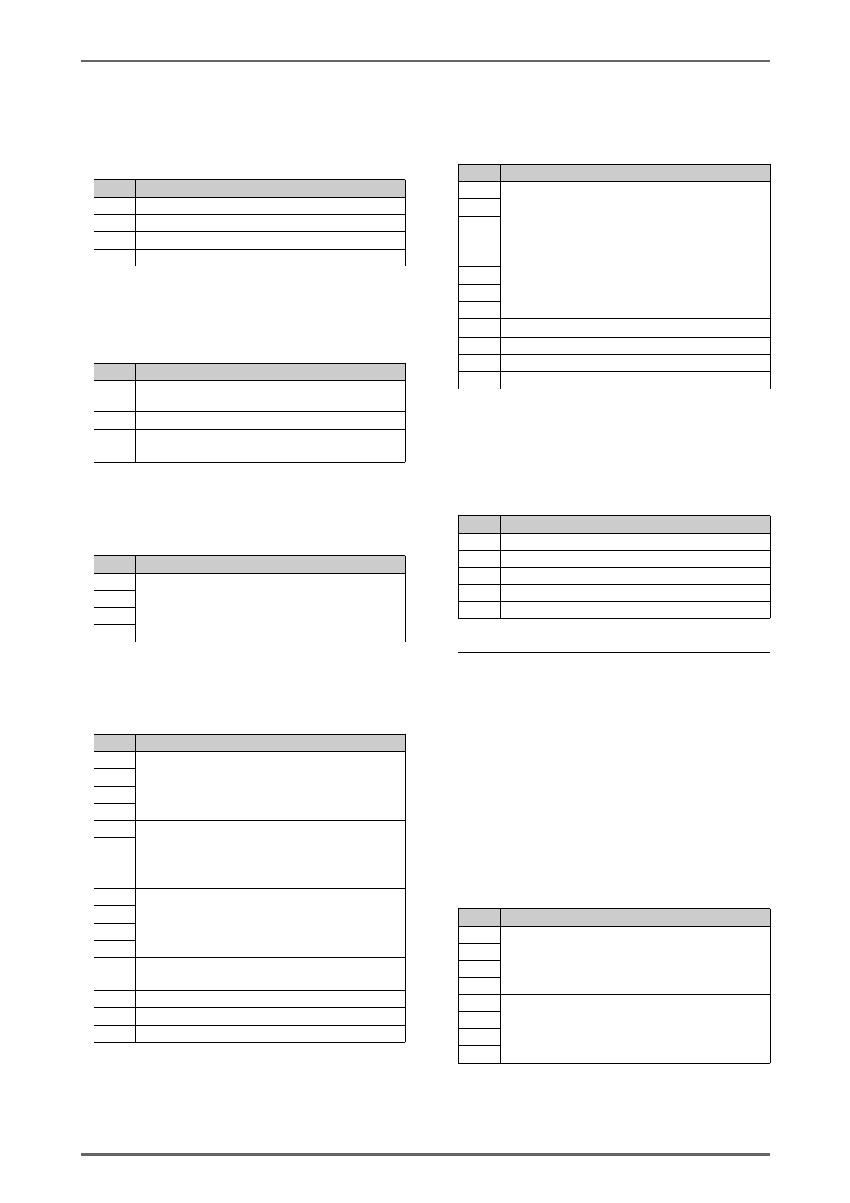
• Storage settings
• Program name
• Measurement area details
The correction target selection of feature point
correction of position correction and the unique
parameters of the measurement target of the
measurement mode are shown below.The byte
numbers shown here indicate the byte numbers from
the start of the corresponding data block. (see the
example at 12.4)
Type:10h~1Fh (10h:Program NO.0, 11h:Program NO.1,
, 1F:Program NO.15)
Category:08h, Item:01h
Target1~4:00h
byte
Setting Data
0
Storage target: 0:OFF, 1:OUT value, 2:Profile
1
Reserved (fixed as 0)
2
Reserved (fixed as 0)
3
Reserved (fixed as 0)
Type:10h~1Fh (10h:Program NO.0, 11h:Program NO.1,
, 1F:Program NO.15)
Category:08h, Item:02h
Target1~4:00h
byte
Setting Data
0
Storage condition: 0:Terminal/Command, 1: OUT
update, 2:OUT data (edge), 3:OUT data (level)
1
Reserved (fixed as 0)
2
Reserved (fixed as 0)
3
Reserved (fixed as 0)
Type:10h~1Fh (10h:Program NO.0, 11h:Program NO.1,
, 1F:Program NO.15)
Category:08h, Item:03h
Target1~4:00h
byte
Setting Data
0
Storage data amount: 0 to buffer size upper limit.
*Upper limit value is the max points can be set by LJ-
Navigator2.
1
2
3
Type:10h~1Fh (10h:Program NO.0, 11h:Program NO.1,
, 1F:Program NO.15)
Category:08h, Item:04h
Target1~4:00h
byte
Setting Data
0
Storage data amount: 0 to buffer size upper limit.
*Upper limit value is the max points can be set by LJ-
Navigator2.
1
2
3
4
Threshold: The range that can be input in the OUT
minimum display unit. (0.01μm unit. Sined 32-bit
integer)
5
6
7
8
Hysteresis: 0 Hysteresis display range upper
limit for the minimum display unit. (0.01μm unit.
Sined 32-bit integer)
9
10
11
12
Target OUT: 0:OUT1, 1:OUT2,
2:OUT3
15:OUT16
13
Edgedirection: 0:Rising, 1:Falling
14
Reserved (fixed as 0)
15
Reserved (fixed as 0)
Type:10h~1Fh (10h:Program NO.0, 11h:Program NO.1,
, 1F:Program NO.15)
Category:08h, Item:05h
Target1~4:00h
byte
Setting Data
0
Upper limit value: The range that can be input in
the OUT minimum display unit. (0.01μm unit.
Sined 32-bit integer)
1
2
3
4
Lower limit value: The range that can be input in
the OUT minimum display unit. (0.01μm unit.
Sined 32-bit integer)
5
6
7
8
Target OUT: 0:OUT1, 1:OUT2
15:OUT16
9
Reserved (fixed as 0)
10
Reserved (fixed as 0)
11
Reserved (fixed as 0)
Type:10h~1Fh (10h:Program NO.0, 11h:Program NO.1,
, 1F:Program NO.15)
Category:09h, Item:00h
Target1~4:00h
byte
Setting Data
0
Program name, byte0
1
Program name, byte1
2
Program name, byte2
~
~
23
Program name, byte23
* 24 characters max. 0 is not appended to the end.
* SHIFT-JIS
0:Peak, 1:bottom, 6:Average, 8:Maximum thickness,
9:Minimum thickness, 10:Average thickness, 11:Maximum
thickness position, 12:Mimimum thickness position,
13:Middle value, 14:P-P (Z) (only when profile compression
(time axis) is on),16:P-P (only for Height (simple 3D)
byte
Setting Data
0
Area Left: any value in measurement range
(0.01μm unit Sined 32-bit integer
example: 5mm=500000)
1
2
3
4
Area Right: any value in measurement range
(0.01μm unit Sined 32-bit integer
example: 5mm=500000)
5
6
7