4 tolerance limit value setting – KEYENCE EX-V Series User Manual
Page 35
Chapter 2 Quick Guide to Basic Mode Operation
2
25
2.4
Tolerance Limit Value Setting
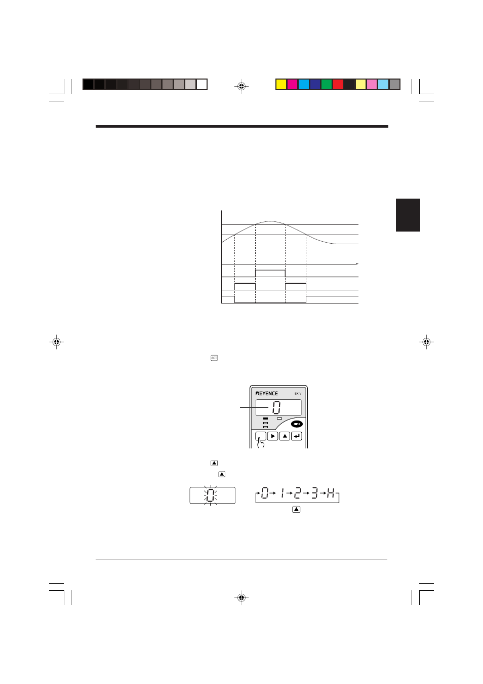
You can set the allowable range for the tolerance limit value. After the comparator
of measured values, signals are output at three levels: when the measured value
exceeds the upper limit (HIGH), when it is below the lower limit (LOW), and when it
is within the allowable range (GO). The measured value is displayed in green for
the GO output and in red for the HIGH and LOW outputs.
Operation diagram
Setting the tolerance limit values
1. Press the
key.
•
The sensor enters the tolerance limit setting mode.
•
The setting number is displayed.
2. Press the
key to display the desired setting number.
Pressing the
key changes the setting number sequentially.
ON
OFF
ON
OFF
ON
OFF
(v)
(t)
*
*
HIGH OUT
GO OUT
LOW OUT
HIGH limit value
LOW limit value
Displayed value
When a signal is output, the comparator output indicator on the
controller’s front panel illuminates.
* With the factory setting, a hysteresis of 5 digits is applied
when the output changes from LOW to GO or HIGH to GO.
SET
CALL
HIGH
TIM
GO
LOW
FUNC
UTILITY
MODE
CALIB
key
Setting No.