KEYENCE EX-V Series User Manual
Page 25
Chapter 2 Quick Guide to Basic Mode Operation
2
15
*
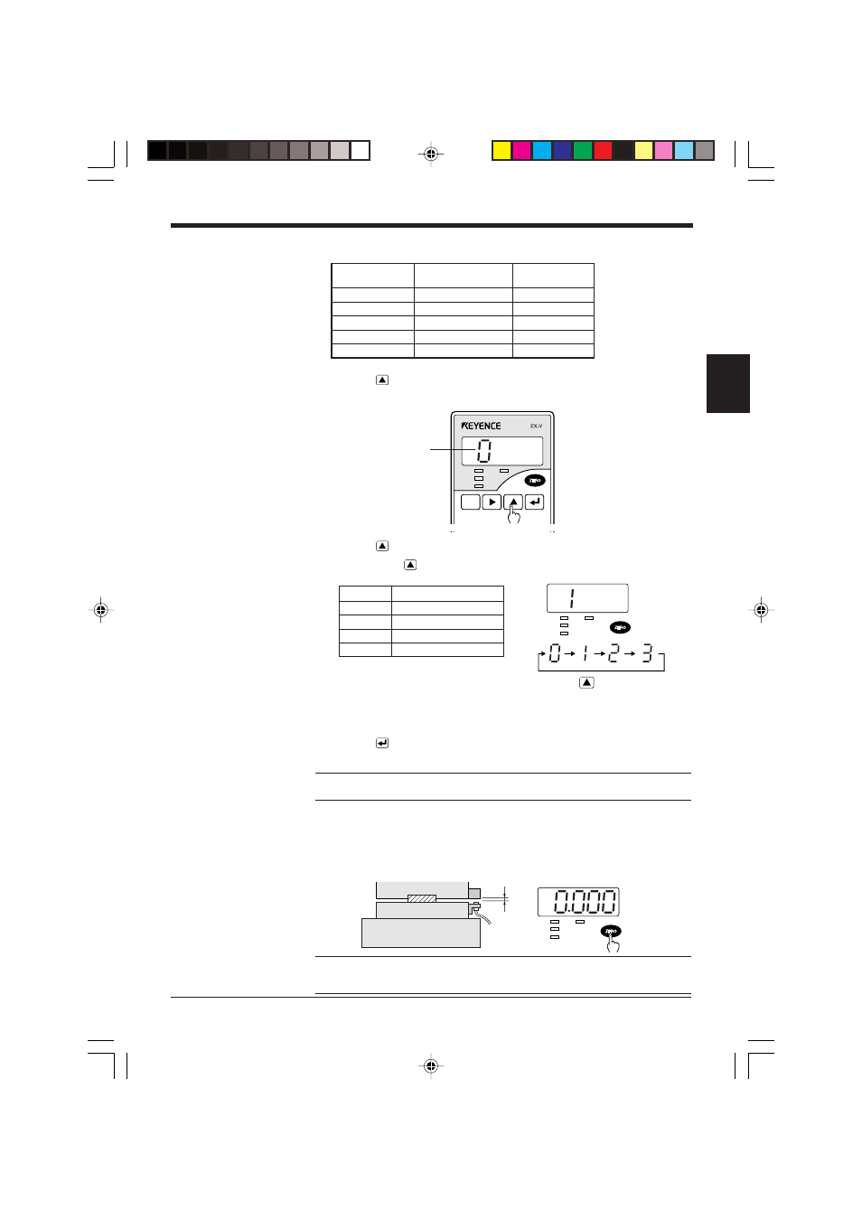
The distance between the sensor head and target should be more than the full scale when the
stripper is in the top dead center position.
3. Press the
key for at least 2 seconds.
The sensor enters the mode setting state and displays the mode number.
4. Press the
key to display “1” which indicates the “bottom-dead-center” mode.
•
Pressing the
key changes the mode number sequentially.
•
The measurement mode is factory-set to manual.
➮ For the initial setting of each measurement mode, refer to “4.1 Table of Data Processing
Functions” on page 46.
5. Press the
key to save the measurement mode setting.
The sensor returns to the measurement state.
Note: Changing the measurement mode initializes all preset values except for the
tolerance limit values.
6. Activate the machine and check the bottom dead center position during normal
operation. Press the [ZERO] key to set this position as the reference point.
When the [ZERO] key is pressed, “0000” appears on the measured value
display.
Reference: To compensate for the slight variation in the bottom dead center
position at press startup or the influence of temperature fluctuation, refer to “Previ-
ous value comparison function [d]” on page 56.
SET
CALL
HIGH
TIM
GO
LOW
FUNC
UTILITY
MODE
CALIB
Sensor model
Measuring distance
Half scale
(mm) (Full scale)
(mm)
EX-305V
1
0.5
EX-110V
2
1
EX-416V
5
2.5
EX-422V
10
5
EX-614V
4
2
Mode No
HIGH
TIM
GO
LOW
key
Mode No.
Measurement mode
0
Manual
1
Bottom-dead-cente
2
Eccentricity/vibration
3
Thickness/gap
HIGH
TIM
GO
LOW
Stripper or upper die
Die set
Lower die
Normal bottom
dead center