Connections, 1 receiver, 6wiring – Pilz PSENvip RL D P User Manual
Page 77: 2 connections
6.2
Connections
6
Wiring
Pilz GmbH & Co. KG, Felix-Wankel-Straße 2, 73760 Ostfildern, Germany
Telephone: +49 711 3409-0, Telefax: +49 711 3409-133, E-Mail: [email protected]
6-4
6.2
Connections
6200
Connections
6-
6.2.1
Receiver
Receiver
6-
Funktion_Geraete_Empfaenger_Stecker
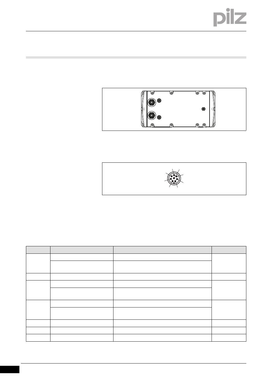
The top of the receiver has two 8-pin M12 connectors.
Verdrahtung_Anschluss_Empfaenger
Fig. 6-2:
M12 connector on the receiver
The receiver is connected via two 8-pin cables.
Fig. 6-3:
Receiver's pin assignment
The cable ends of the Pilz ready-made cable are colour-coded. Please
refer to the tables below for the coding details.
Verdrahtung_Anschluss_Empfaenger_Basis
Pin assignment of M12 connector X1 on the receiver
PIn No.
Designation
Description
Colour
1
Overrun measurement 1
Output, result of overrun measurement
White
Tool class PSENvip -> PLC Bit 1
*)
Output, sends tool class Bit 1 to safety system
2
24 VDC
Input, 24 VDC supply voltage
Brown
3
Protected field mode 1
Input, setting of protected field modes
Green
Tool class PLC -> PSENvip Bit 1
*)
Input, safety system reflects tool class Bit 1
4
Protected field mode 2
Input, setting of protected field modes
Yellow
Tool class PLC -> PSENvip Bit 2
*)
Input, safety system reflects tool class Bit 2
5
OSSD1
Output, OSSD1
Grey
6
Activate *)
Output: Start communication with safety system
Pink
7
0 V
Input, 0 V supply voltage
Blue
X1
X2
1
2
3
4
8
5
6
7