3 led, 4function description, 4 description of the units – Pilz PSENvip RL D P User Manual
Page 44
Pilz GmbH & Co. KG, Felix-Wankel-Straße 2, 73760 Ostfildern, Germany
Telephone: +49 711 3409-0, Telefax: +49 711 3409-133, E-Mail: [email protected]
4-17
4.4
Description of the units
4
Function Description
][Funktionsbeschreibung_BA_Zusatz Einschalttest
Funktion_Geraete_Empfaenger_Ausgang_NLW
Overrun measurement
Safe output that reports the result of the measurement of the overrun
to the programmable safety system.
Overrun measurement = 1: Overrun within the specified range
Overrun measurement = 0: Overrun outside the specified range.
Overrun is too long.
The overrun is measured each time the protected field is interrupted.
The overrun measurement output is set to “0” as soon as the protect-
ed field has been cleared.
Funktion_Geraete_Empfaenger_Ausgang_Zusatz
4.4.3.3
LED
LED
4-
Funktion_Geraete_Empfaenger_LED_OSSD
OSSD
The OSSD LED on the receiver indicates the status of the protected
field.
Green: The protected field is clear
Red: Protected field is interrupted
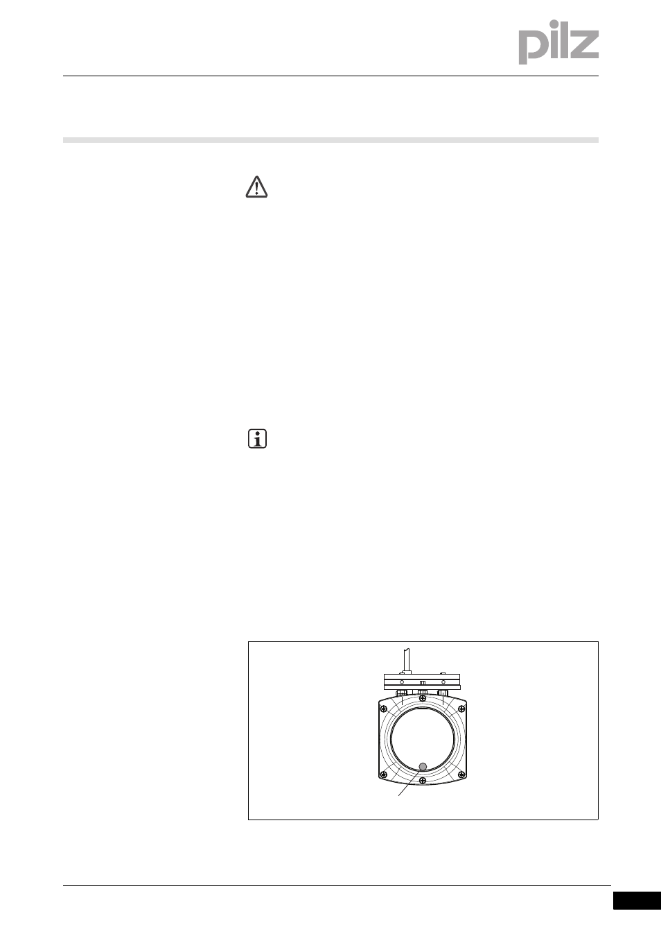
Funktion_Geraete_Empfaenger_LED_RL_D_Abbildung
Fig. 4-8:
LED on receiver
1: OSSD LED
WARNING!
When wiring an output with capacitance it is essential to note
the pulse duration, repetition period and scan time of the power-
up test, otherwise the load may switch on unintentionally.
INFORMATION
The outputs for overrun measurement have another function
during the system status TEST. They are used for communica-
tion with the safety system. See "Communication with a safety
system" in this section.
1