2 transmitter, 1 inputs, 4function description – Pilz PSENvip RL D P User Manual
Page 40: 4 description of the units
Pilz GmbH & Co. KG, Felix-Wankel-Straße 2, 73760 Ostfildern, Germany
Telephone: +49 711 3409-0, Telefax: +49 711 3409-133, E-Mail: [email protected]
4-13
4.4
Description of the units
4
Function Description
Funktion_Geraete_Sender_Empfaenger_RL_D
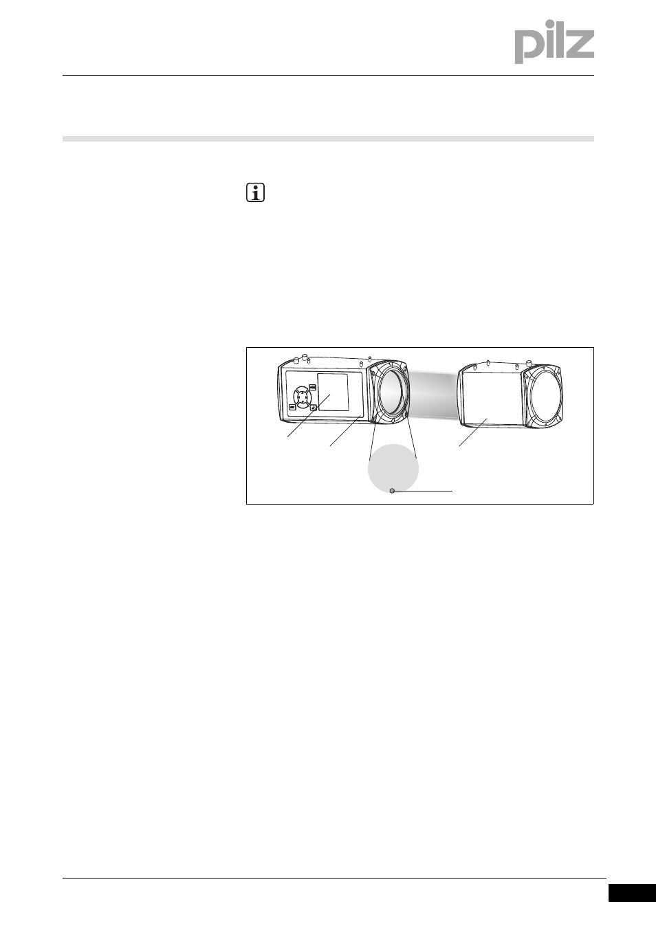
Fig. 4-6:
Transmitter and receiver
1: Display
2: Receiver
3: LED: OSSD status
4: Transmitter
4.4.2
Transmitter
Transmitter
4-
Funktion_Geraete_Sender_Stecker
The top of the transmitter has a 4-pin M12 connector.
4.4.2.1
Inputs
Inputs
4-
Funktion_Geraete_Sender_Eingang_TRM_ON_TRM_SYNC
The receiver uses these standard inputs to control the transmitter's light
source. The user cannot influence these internal signals.
TRM_ON
The receiver uses this signal to switch the transmitter's light source
on and off.
INFORMATION
Some inputs and outputs on the receiver are also used for com-
munication with the safety system (see section entitled "Com-
munication with the safety system"). If communication is not
required, protected field mode can also be controlled directly via
the CNC controller.
1
2
3
4