Rockwell Automation AADvance Controller Safety Manual User Manual
Page 42
3-8
Document: 553630
ICSTT-RM446K-EN-P Issue: 10
_C
Safety Manual (AADvance Controller)
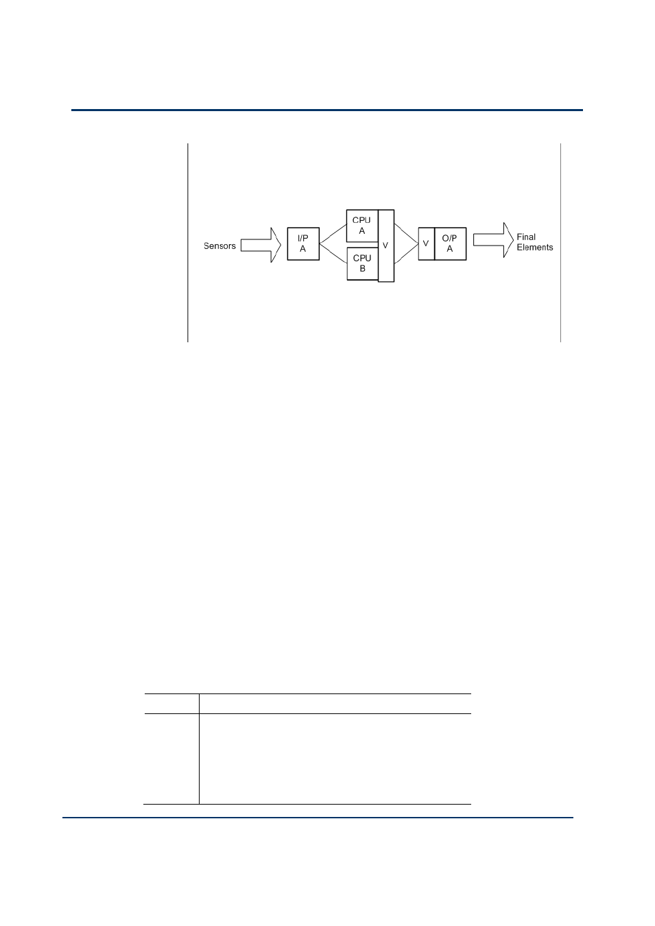
If required you can configure triple processor modules as a variation of this
SIL3 architecture. Using this arrangement the processor modules operate in
2oo3D under no fault conditions and 1oo2D on the detection of the first fault
in any module. They degrade to 1oo1D on the detection of faults in any two
modules, and will fail-safe when there are faults on all three modules.
Digital Output Modules
For de-energize to action operation one digital output module is sufficient
for SIL3 requirements. However, for energize to action operation, dual
digital output modules are required.
A digital output module fault must be repaired within the MTTR which was
used in the PFD calculation.
Analogue Output Modules
The fail-safe state current of the analogue output module is less than 2mA.
For de-energize to action operation one analogue output module
is sufficient for SIL3 requirements. However, for energize to action
operation, dual analogue output modules are required.
A analogue output module fault must be repaired within the MTTR
which was used in the PFD calculation.
Table 7:
Modules for SIL3 Fail-safe I/O, Fault Tolerant Processor
Position Module Type
I/P A
T9401/2 Digital Input Module, 24V c, 8/16 Channel +
T9801 Digital Input TA, 16 Channel, Simplex or
T9431/2 Analogue Input Module, 8/16 channel + T9831
Analogue Input TA, 16 Channel, Simplex
T9300 Base unit