Ppendix, Compliance with eu requirements – Rockwell Automation SP200 AC Drive, 1 2 Channel Analog, Preset Speed User Manual
Page 57
Compliance with EU Requirements
C-1
A
PPENDIX
C
Compliance with EU Requirements
The SP200 drive is CE-marked for Low Voltage (LV) Directive 73/23/EEC and all
applicable standards when installed as described within the Low Voltage section that
follows. It also has been tested to meet Electromagnetic Compatibility (EMC) Directive
89/336/EEC when installed as described within the Electromagnetic Compatibility
section that follows. Contact the Rockwell AutoFax service in the United States at
440-646-7777 (or your local Rockwell Automation office if outside the U.S.) for copies
of the Declaration of Conformity (DOC).
Conformity of the SP200 drive to EU directives does not guarantee that the entire
system will conform. For EMC, many other factors can affect the total installation, and
only direct measurements can verify total conformity. It is the responsibility of the
machine manufacturer (or end user, if the machine is being modified or used beyond
manufacturer’s specifications) to comply.
Low Voltage Directive 72/23/EEC
• Follow all general precautions and ATTENTION statements throughout this
manual.
• Provide an earth ground connection to the PE terminal.
• Install in a protective enclosure which restricts access to IP 20 rated devices as
required by your national and local codes and regulatory agencies.
Electromagnetic Compatibility Directive 89/336/EEC
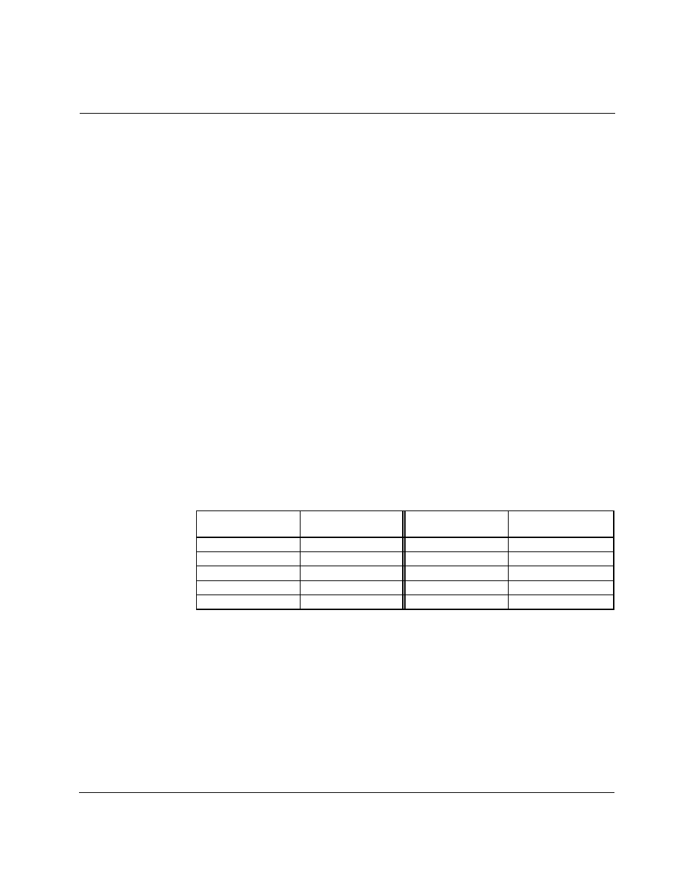
• Install the SP200 drive and Input Mains Filter (as specified in the table below) in a
typical IEC or NEMA metal (shielded) enclosure as shown in the figure on the
following page. Adhere to maximum motor cable lengths as specified in appendix
D or 25 meters, whichever is shorter.
Refer to
SP200 Mains Filters (D2-3420) for filter dimensions and weights.
• Keep all input power, output power, and control signal wiring, both inside and
outside enclosure, physically separate from one another.
• Connect the enclosure to the SP200 PE input (top) terminal.
• Connect the enclosure to earth ground.
• Use shielded cable with a ground conductor or individual conductors in grounded
metal conduit for motor power wiring on the output side of the drive, both inside
and outside the enclosure, all the way to the motor. Bring the shield as close to the
output power terminals as possible. Connect the motor cable ground and shield to
the ground terminal on the output (bottom) side of the SP200 drive. Connect the
opposite end of the motor cable ground conductor and shield to the motor
housing.
Drive Model
Number
Filter Model
Number
Drive Model
Number
Filter Model
Number
S20-X02P3.....
S20-MF1-Y014
S20-204P2.....
S20-MF1-45P0
S20-X04P2.....
S20-MF1-Y014
S20-207P0.....
S20-MF1-49P5
S20-X06P0.....
S20-MF1-Y014
S20-401P3.....
S20-MF1-45P0
S20-Y07P0.....
S20-MF1-Y014
S20-402P0.....
S20-MF1-45P0
S20-202P3.....
S20-MF1-45P0
S20-402P3.....
S20-MF1-45P0