Hapter, Wire the control signal terminal block – Rockwell Automation SP200 AC Drive, 1 2 Channel Analog, Preset Speed User Manual
Page 15
Wire the Control Signal Terminal Block
5-1
C
HAPTER
5
Wire the Control Signal Terminal Block
The following sections describe how to wire the control signal terminal block. (Refer to
figure 1.1 for the location of the terminal block).
Refer to figure 5.2 (Model A, Single Channel Analog), 5.3 (Model B, Preset Speed), or
5.4 (Model C, Dual Channel Analog) before you begin wiring. These figures show
typical wiring connections.
Note the following when wiring the terminal block:
• The terminal block is isolated from the input power.
• Control wires should be routed separately from the power wires.
• The terminal block accepts 1.5 mm
2
(16 AWG) through 0.14 mm
2
(26 AWG) wire.
• The maximum control wire length is 30 meters (100 ft
).
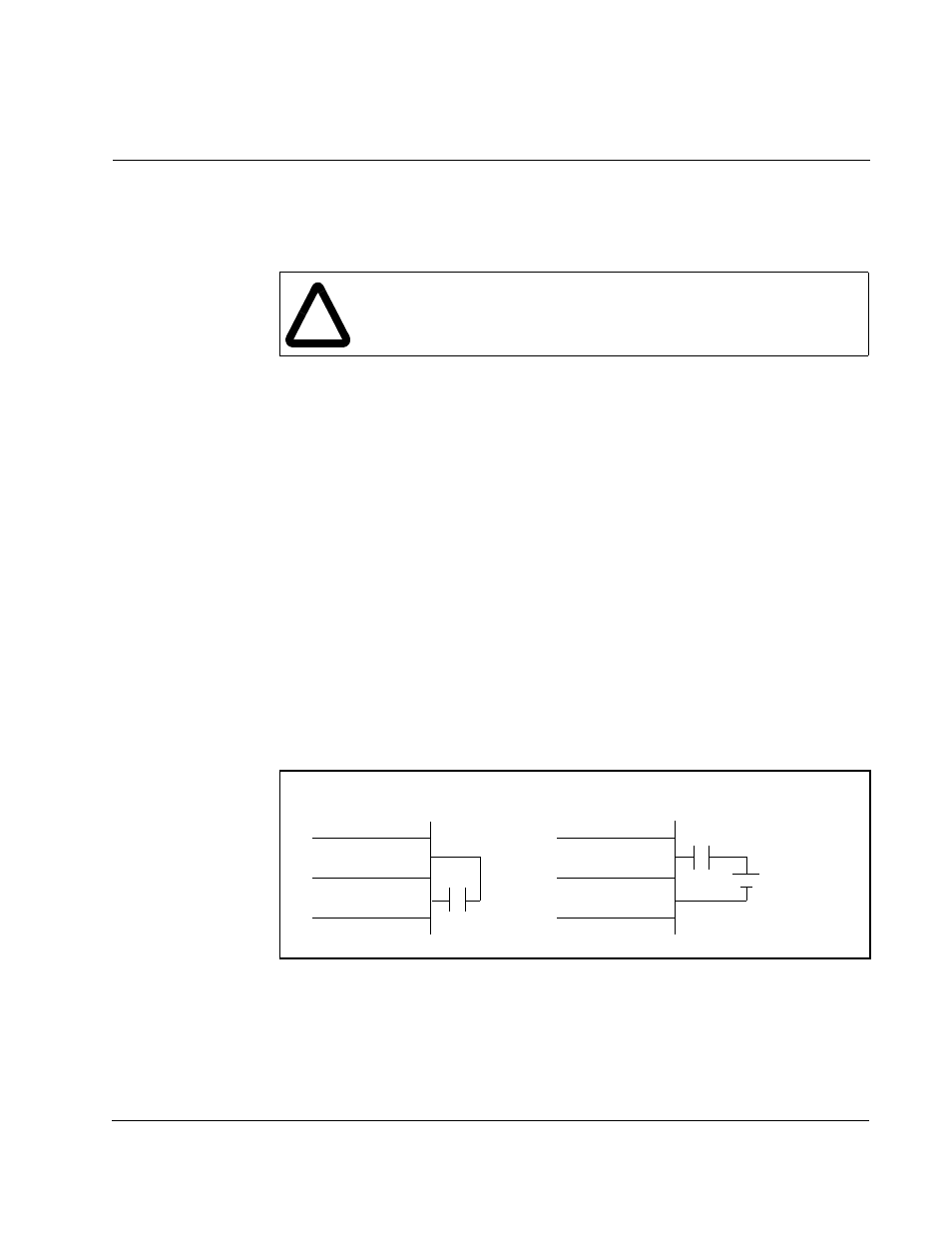
The SP200 drive’s digital control inputs can be activiated by either its own +10 VDC
supply or an external supply rated between 10 and 24 VDC. Figures 5.2, 5.3, and 5.4
show connections using the drive’s +10 V supply. If you are using an external supply,
connect each digital input as shown in the external supply method shown in figure 5.1.
!
ATTENTION: If 2-wire control is selected, the drive will immediately run
when powered up in the presence of a forward or reverse run command.
Failure to observe this precaution could result in severe bodily injury or
loss of life.
Figure 5.1 – Supply Methods for Digital (Switch) Input Connections
Internal Supply Method
External Supply Method
+10 VDC
Digital (Switch)
Inputs
Shield/Common
(Terminal 1)
Digital (Switch)
Inputs
10 to 24 VDC
+
_