Rockwell Automation SP200 AC Drive, 1 2 Channel Analog, Preset Speed User Manual
Page 36
7-14
Installing and Operating the SP200 AC Drive
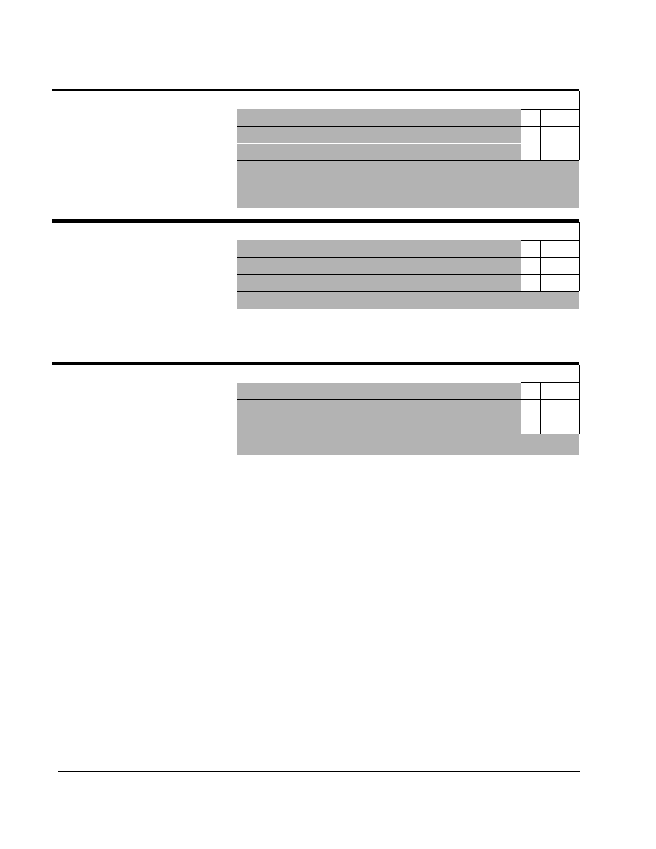
P-35 DC Brake Current
Model
A
B
C
Use this parameter to specify the
output current level that is applied to
the motor during DC injection braking.
Important: DC injection braking can
cause motor thermal failure if used
improperly or excessively.
Parameter Range:
10 to 150 (%)
X
X
X
Default Setting:
50
X
X
X
Running Access:
RW
P-36 DC Brake Time at Stop
Model
A
B
C
Use this parameter to specify the time
that DC injection braking at the level
specified in P-35 (DC Brake Current)
will be applied to the motor.
If P-34
Parameter Range:
0 to 20.0 (x.x seconds)
X
X
X
Default Setting:
0.5
X
X
X
Running Access:
RW
(Stop Control) is set to 0 to select ramp- to- stop, DC injection braking begins after the drive is stopped and the output
frequency has ramped down to zero. If P-34 (Stop Mode) is set to 2 to select DC injection braking, it begins immediately
when the drive is commanded to stop.
P-37 Avoidance Frequency
Model
A
B
C
Use this parameter, along with P-38
(Avoidance Frequency Band), to
prevent the drive from continuous
operation within a range (band) of
Parameter Range:
0 to 240.0 (x.x Hz)
X
X
X
Default Setting:
0 (disabled)
X
X
X
Running Access:
RW
frequencies. This may be useful to prevent continuous operation at undesirable speeds. This parameter
specifies the midpoint of the frequency avoidance band specified by P-38 (Avoidance Frequency Band). A
zero value disables this function.