Rockwell Automation SP200 AC Drive, 1 2 Channel Analog, Preset Speed User Manual
Page 51
Diagnostics and Troubleshooting
9-3
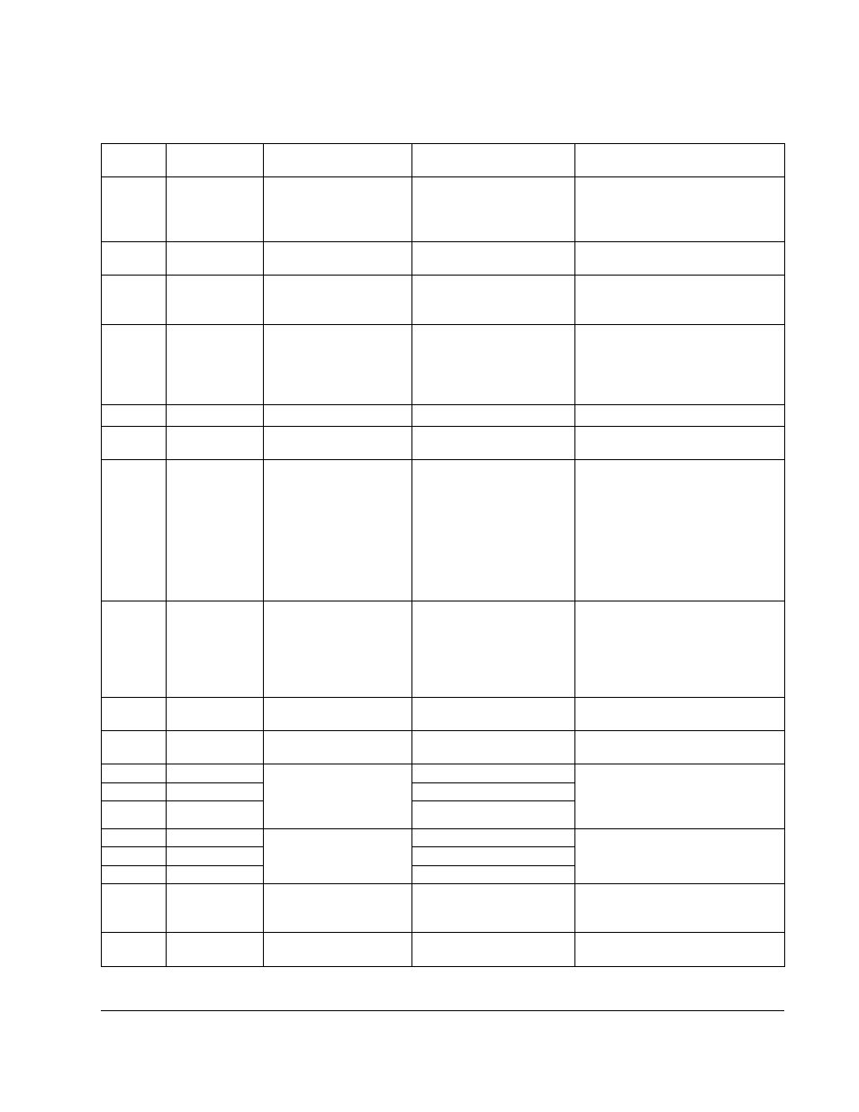
Table 9.2 – Fault Codes and Corrective Actions
Display
Code
No. of Fault
LED Flashes
Fault Description
Fault Cause
Corrective Action
CF
2
Control Input
Illegal control input
sequence.
- 3-wire: Verify Start and Jog inputs
are not both ON.
- 2-wire: Verify that only one input
(Forward, Reverse, or Jog) is on.
FL
2
Function Loss
Start attempt while STOP
(Function Loss) input is off.
Verify STOP (Function Loss) input is
ON before attempting to start drive.
LU
3
Under Voltage
1
1
Auto Resettable
- Low input line.
- Temporary loss of
input line.
Check input line to verify voltage is
within operating specifications.
HU
4
Over Voltage
- High input line.
- Decel time too fast.
- Overhauling load.
- Check input line to verify
voltage is within operating
specifications.
- Increase decel time.
dO
5
Drive Overload
Excessive driven load.
Reduce the load.
OL
5
Motor Overload
Excessive driven load.
- Verify P-02 is set correctly.
- Reduce the load.
OH
6
Over Temperature
- Operating environment
is too hot.
- Fan is blocked or not
operating.
- Excessive driven load.
- Verify the ambient
temperature is < 50 °.
- Verify clearance above/ below
drive.
- Check for fan obstruction. Replace
fan if required.
- Reduce the carrier frequency (P-
64).
- Reduce the load.
OC
7
Over Current
(300%)
- Shaft rotation blocked.
- Excessive driven load.
- Output wiring is incorrect
or shorted.
- Check for obstructions to
shaft rotation or reduce
excessive load.
- Increase accel / decel time.
- Verify output wiring is correct.
CL
8
Bad Keypad Connection
Bad connection from
keypad to drive.
Verify keypad is properly connected
to drive.
UF
9
Negative Slope
Conflicting parameter
values.
Adjust values of parameters -P-50
through P-54.
J1
10
Ground Short
Phase U
- Verify output wiring is correct
- Verify output phase is not
grounded.
- Verify motor is not damaged.
J2
10
Phase V
J3
10
Phase W
J4
10
Phase to Phase Short
Phase U - V
- Verify output wiring is correct.
- Verify motor is not damaged.
J5
10
Phase U - W
J6
10
Phase V - W
CH
11
Checksum Failure
Parameter value out of
range.
Load default parameter values (P-
60 =1), then cycle power. If fault
persists, replace drive.
UP
12
Microprocessor Fault
Internal processor error.
Cycle power. If fault persists,
replace drive.