Rockwell Automation SP200 AC Drive, 1 2 Channel Analog, Preset Speed User Manual
Page 31
Editing Drive Parameters
7-9
7.1.3.2 Selecting the Speed Reference for Model C Drives
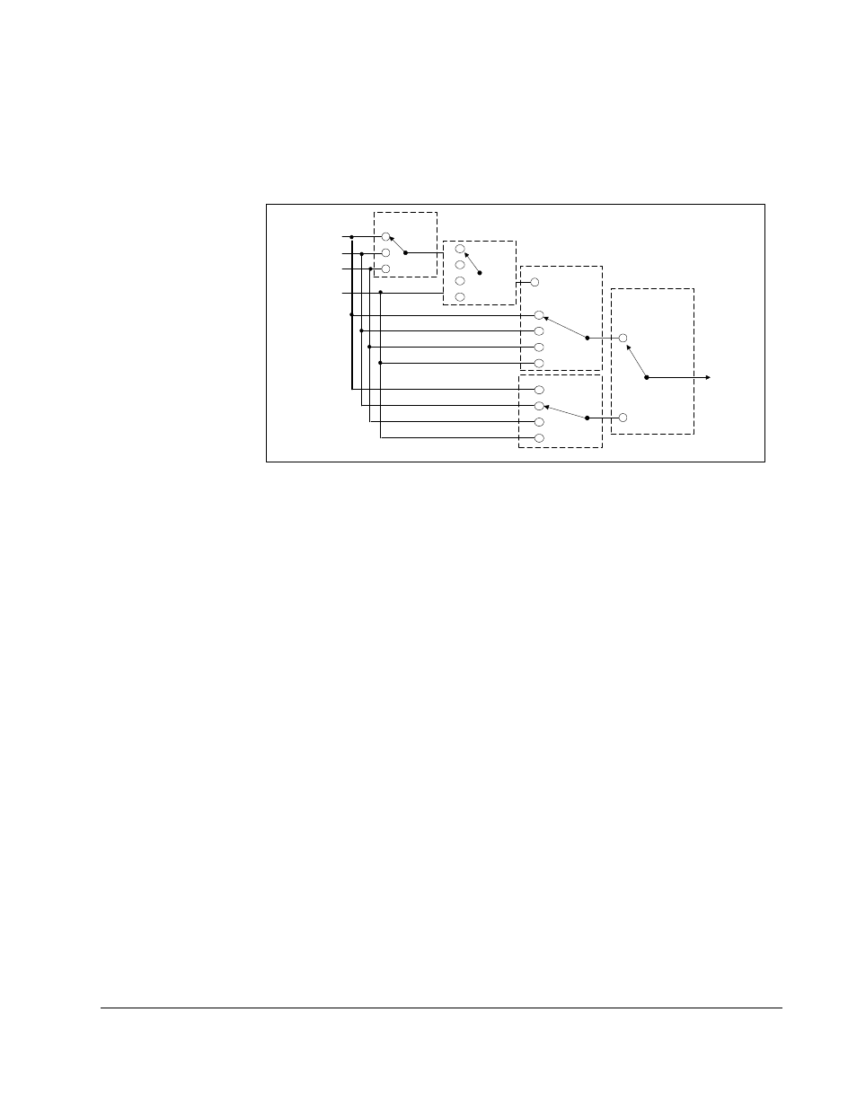
Figure 7.2 shows the logic that is used to establish the source of the speed reference
for model C drives. See the parameter descriptions for additional configuration
information.
Figure 7.3 – Speed Reference Source for Model C Drives
7.1.3.3 Speed Selection Examples
Following are two examples of setting the speed reference for SP200 drives.
Example 1
Configure the drive to use two speed references : P-40 (Internal/Jog Frequency) and
the keypad frequency. Use the Configurable Input to switch between these two speed
references so that when it is turned on, P-40 (Internal/Jog Frequency) is selected.
This is accomplished as follows:
Step 1. Set P-20 (Main Speed Reference) = 1 to select the keypad frequency as the
main speed reference.
Step 2. Set P-21 (Alternate Speed Reference) = 2 to select P-40 (Internal/Jog
Frequency) as the alternate speed reference.
Step 3. Set P-11 (Configurable Input) = 3 to select the alternate speed reference
enable function. When the configurable input is turned on, P-40 (Internal/
Jog Frequency) is selected as the active speed reference for the drive.
Example 2 (Model C only)
Configure the drive to use PI control. The reference for the process is Analog Input 2.
This is accomplished as follows :
Step 1. Set P-28 (Process Reference) = 0 to select Analog Input 1 as the process
reference.
Analog Input 1
Keypad Frequency
Internal Frequency
Analog Input 2
0
1
2
0
1
2
3
0
1
2
3
4
0
1
2
3
(P-20)
Main
Speed
Ref
Alternate
Speed
Ref
(P-21)
Process Ref
Select
(P-28)
Speed
Reference
Configurable
Input
(P-11 = 3)
(P-29)
Process
Operation