Rockwell Automation GV3000/SE AC Gen. Purpose and Vector Drive Software Start-Up and Ref. Manual User Manual
Page 71
Starting Up the Drive for Vector Regulation
2-33
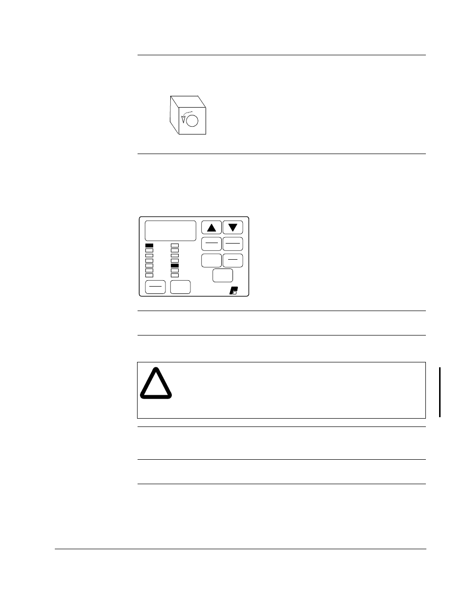
Step 10.8 Visually check that the motor rotates counter-clockwise (CCW) when
viewed from the driven motor shaft end.
Step 10.9
•
If the rotation direction is NOT correct, press the STOP/RESET key and continue
with step 10.10.
•
If the rotation direction is correct, continue with step 10.14.
When the STOP/RESET key is pressed, the
RUNNING LED turns off.
Step 10.10 Turn off and lock out or tag power to the drive.
Step 10.11 Verify that the DC bus capacitors are discharged. Refer to the hardware
reference manual for this procedure.
Step 10.12 Switch any two of the motor leads (U, V, or W) and A and A NOT on the
encoder (if an encoder is used).
Step 10.13 Turn power on, and press the START key. Repeat step 10.8.
Step 10.14 To make sure the drive is not inadvertently started, turn off and lock out
or tag power to the drive. Verify that the motor direction is appropriate
for the required machine direction, and then connect the motor to the
load.
CCW
)RUZDUG
5HYHUVH
$872
0$1
(17(5
581
-2*
PROGRAM
67$57
6723
5(6(7
63(('
92/76
$036
+]
.Z
72548(
3DVVZRUG
5811,1*
5(027(
-2*
$872
)25:$5'
5(9(56(
352*5$0
5(/,$1&(
(/(&75,&
!
ATTENTION: DC bus capacitors retain hazardous voltages after input
power has been disconnected. After disconnecting input power, wait five
(5) minutes for the DC bus capacitors to discharge and then check the
voltage with a voltmeter to ensure the DC bus capacitors are discharged
before touching any internal components. Failure to observe this
precaution could result in severe bodily injury or loss of life.