Disconnect power from the terminal, Disconnect all power and communication cables, If reusing the memory in the new logic module – Rockwell Automation 2711P PanelView Plus Terminal User Manual User Manual
Page 146: Install the new logic module, Attach the communication module, if necessary
146
Publication 2711P-UM001J-EN-P - November 2009
Chapter 6 Install and Replace Components
Before replacing the logic module, you must remove the
communication module, if attached. You will also need to remove the
Internal RAM and CompactFlash from the logic module to reuse in the
new logic module.
Follow these steps to replace a logic module.
1. Disconnect power from the terminal.
2. Disconnect all power and communication cables.
3. Set the terminal, display side down, on a clean, flat, stable
surface to prevent scratches, if the terminal is removed from
panel.
4. Remove the four screws that attach the communication module,
if attached, to the logic module and carefully lift the
communication module away from the logic module.
5. Loosen the six captive screws that secure the logic module to
the display module.
6. Carefully lift the logic module away from the back of the display
module.
7. If reusing the memory in the new logic module:
•
remove the RAM and internal CompactFlash from the logic
module.
•
insert the RAM and internal CompactFlash in the new logic
module.
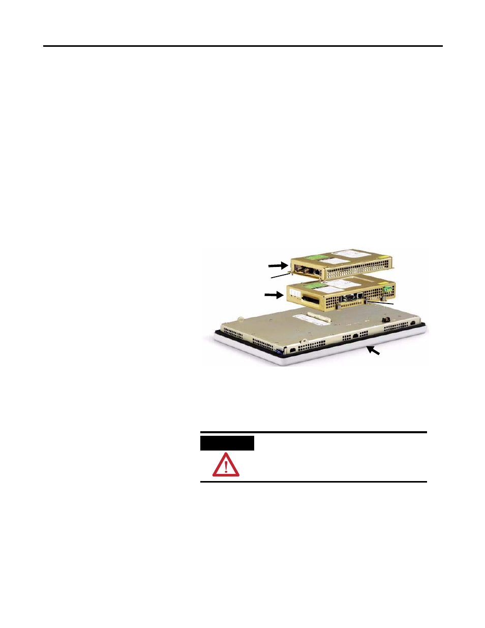
8. Install the new logic module.
9. Attach the communication module, if necessary.
Logic Module
Communication Module
Display Module
Captive Screw
Screw
ATTENTION
Wear a properly grounded ESD wristband before
touching any of the electronic components in the
logic module.