Rockwell Automation 1775-S4B,D17756.5.3 User Manual SCANNER/MSG HND User Manual
Page 46
Getting Started in Report Generation
Chapter 5
5Ć8
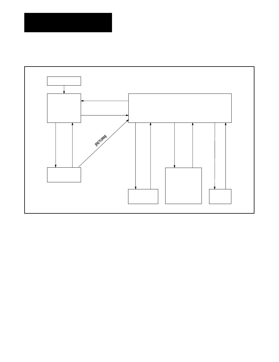
Figure 5.4
Report Generation Control Modes
MSG Instruction
Initialization
Ladder
Diagram
Program
in
Control
Print or
Execute
Procedure
Command Mode in Control
S4B> is output to the data terminal to prompt
the operator upon return to this mode after
completing a command and after each [RETURN].
Execute
Procedure
Edit
Mode
•
•
Directory
•
Create
•
Delete
•
Copy
•
Rename
Procedure completed
@
[BREAK] or [CTRL] [X] or
Procedure completed
Direct Command
Completed
ED @
[BREAK] or [CTRL] [X]
[RETURN]
E [RETURN]
When you turn on your PLC-3 processor it initializes with ladder diagram
mode in control. So if you connect an RS-232-C device to the channel 5
connector on the 1775-S4B scanner, report generation procedures sent
from MSG instructions in your ladder diagram program will execute at the
RS-232-C device. When a procedure completes executing, ladder diagram
mode remains in control. Thus, you can execute consecutive procedures
from the ladder diagram program.
Now if you press [ENTER] or [RETURN] after initialization or after a
message procedure has been executed, the S4B> prompt displays at the
RS-232-C device. This prompt indicates that the command mode is in
control. In command mode, you can execute or edit report generation
procedures or enter report generation commands from your keyboard to
operate report generation. We describe report generation operation in the
following chapters. The report generation commands listed in figure 5.4
are described in chapter 10.
Now if you press [BREAK] or [CTRL] X while you are in the command
mode, the following message displays: