Formatting module data (writes) chapter 7, Example: default configuration, Example: extending in the positive direction – Rockwell Automation 1771-QB Linear Pos. User Manual
Page 90
Formatting Module Data (WRITES)
Chapter 7
7Ć11
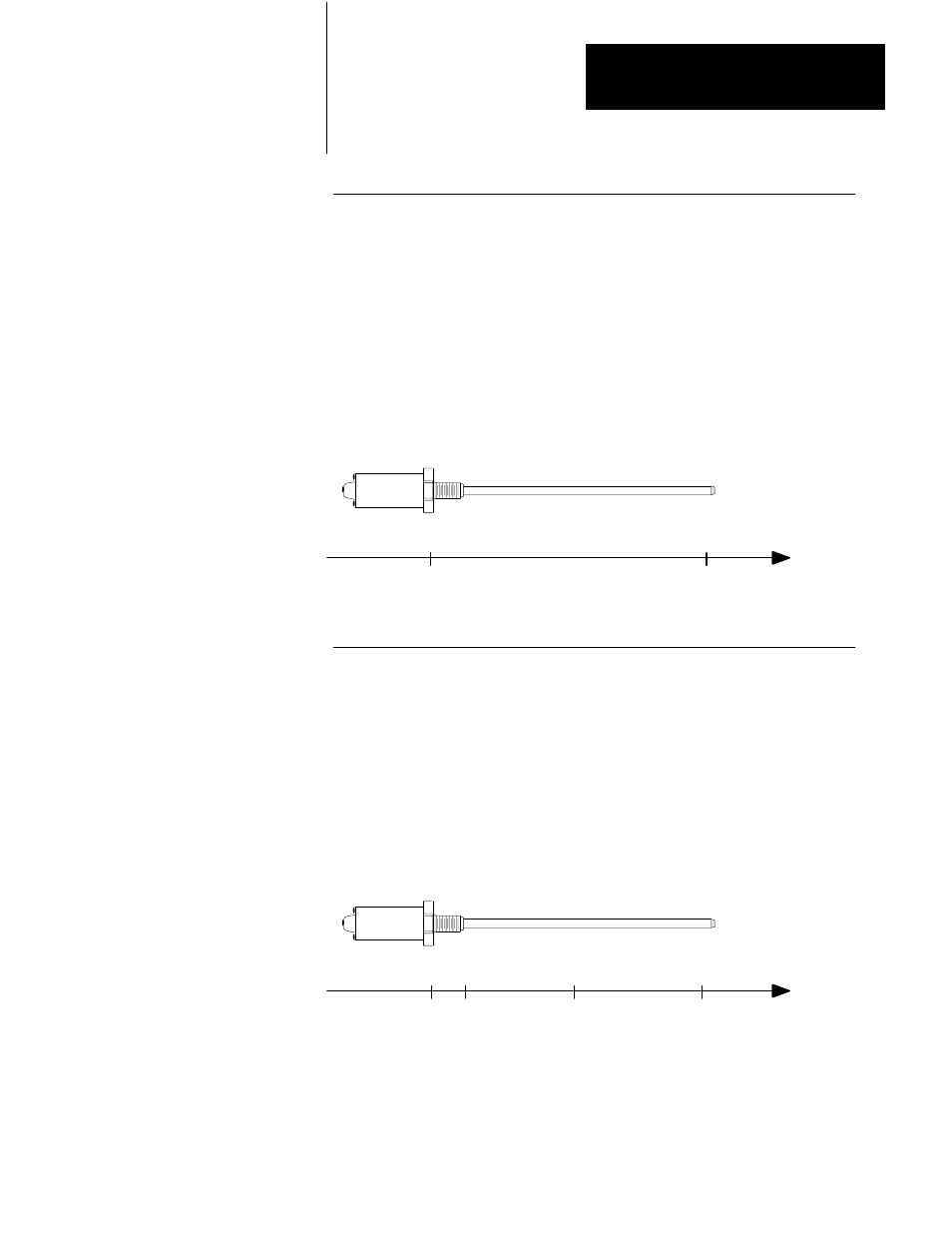
Example: Default Configuration
If the zero-position and software travel limits are 0, all measurements are
relative to the transducer head and the positive direction is towards the end of
the transducer. If you program both software travel limits to 0, the module
defaults to the maximum and minimum that it can measure. In this example, the
negative limit is at the origin and the positive limit is at the maximum distance
that the module can measure: 180 inches for one circulation.
Figure 7.9
Default Configuration
ZeroĆposition = 0.000
Positive Limit = 0.0
Negative Limit = 0.0
Positive
Direction
Pos.
Limit
+180
Neg.
Limit
0
Origin
50012
Example: Extending in the Positive Direction
In this example, the transducer head is -15 inches from the origin. Notice that
all measurements are relative to the origin. The value of the zero position offset
determines the distance between the origin and the transducer head. The sign of
the zero position offset indicates that the transducer head is in the negative
direction.
Figure 7.10
Extending in the Positive Direction
ZeroĆposition = -15.000
Positive Limit = +15.0
Negative Limit = -10.0
Positive
Direction
Pos.
Limit
+15
Origin
Neg.
Limit
-10
-15
50013