Rockwell Automation 1771-QB Linear Pos. User Manual
Page 84
Formatting Module Data (WRITES)
Chapter 7
7Ć5
Bit 7 – Binary Position Format
When bit 7 is set to 1, and binary format is specified in the parameter control
word (bit 3 = 0), the module can display position and error values between
-32.768 and 32.767 inches (-327.68 and 327.67 mm) in the second word of the
position or following error in the status block. This feature allows applications
with a stroke of less than 32 inches to monitor position and error with a single
integer. If the position or error exceeds the maximum, the module automatically
reverts to double word format.
Setting this bit to 0, or selecting BCD format in the parameter control word bit
(bit 3 = 1), configures the module to display position and error in double word
format. The first word displays inches or centimeters and the second word
displays fractions of an inch or centimeter. See Table 7.A.
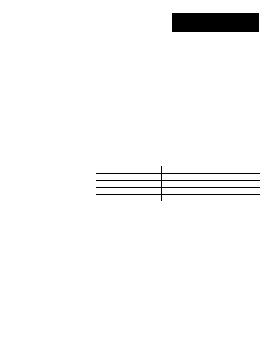
Table 7.A
Single and Double Word Format Representations
Position/Error
Double Word Format
Single Word Format
First Word
Second Word
First Word
Second Word
+6.000 inches
6
0
0
6000
-32.768 inches
-32
-768
0
-32768
327.67 mm
32
767
0
32767
-10.00 mm
-1
0
0
-1000
Bit 8 - Stop/Start Enhancement
When this bit is set, it causes a positive rising edge hardware start input to be
accepted during axis motion, similar to the software start bit in the command
block. Also, as long as the software slide stop bit in the command block is high,
the axis remains stationary since no setpoint (or motion segment if a motion
block is being used), can be initiated. While most new applications can set this
bit, existing applications may clear it to ensure backwards compatibility.
Analog Range (words 2 and 31)
The analog range parameter specifies the maximum analog output available for
commanding motion. It may be positive or negative. Analog range is a
percentage of the range selected through the analog output DIP switches. (See
Chapter 5.) For example, if the analog range is specified as +100%, the direct
action analog output ranges from -10 V to 10 V, -20 mA to 20 mA, -50 mA to
50 mA, or -100 mA to 100 mA, depending on the setting of the analog output
switches. If the analog range is specified as -100%, the reverse action output
ranges from 10 V to -10 V, 20 mA to -20 mA, 50 mA to -50 mA or 100 mA to
-100 mA. Use this parameter to make sure that the module does not exceed the
maximum rating of the external device.