Formatting module data (writes) chapter 7, Figure 7.6 zeroćposition offset, Zeroćposition offset transducer head – Rockwell Automation 1771-QB Linear Pos. User Manual
Page 87: Transducer rod zero position
Formatting Module Data (WRITES)
Chapter 7
7Ć8
Figure 7.5
Transducer Calibration Constant Words
50028
Transducer calibration constant,
BCD or binary
99.9999 microsec/inch or
9.99999 microsec/mm max
Least significant 4 digits
Most significant digits
15 14 13 12 11 10 09 08 07 06 05 04 03 02 01 00
..
.
..
.
...
..
.
..
.
...
..
.
..
.
...
..
.
..
.
...
..
.
..
.
...
..
.
..
.
...
..
.
..
.
...
..
.
..
.
...
..
.
..
.
...
..
.
..
.
...
..
.
..
.
...
..
.
..
.
...
15 14 13 12 11 10 09 08 07 06 05 04 03 02 01 00
..
.
..
.
...
..
.
..
.
...
..
.
..
.
...
..
.
..
.
...
..
.
..
.
...
..
.
..
.
...
..
.
..
.
...
..
.
..
.
...
..
.
..
.
...
..
.
..
.
...
..
.
..
.
...
..
.
..
.
...
0
0
0
0
0
0
0
0
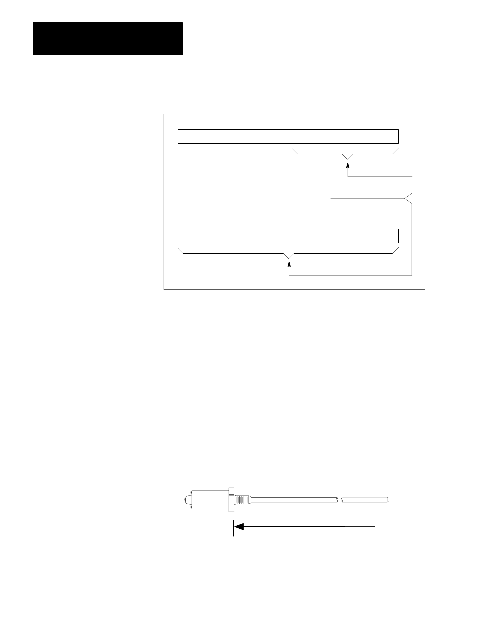
ZeroĆPosition Offset (words 7, 8 and 36, 37)
The zero position offset words define the origin of the coordinate system.
Zero-position can be located within or outside the transducer’s active range.
This allows positions to be measured relative to locations outside the range of
axis motion. The software travel limits and setpoint positions must reside within
the transducer’s active range.
Important: The active range of the transducer is halved by each increase in the
number of circulations of the digital interface box.
Figure 7.6
ZeroĆPosition Offset
50060
ZeroĆposition offset
Transducer
Head
±
Transducer Rod
Zero
position