Formatting module data (writes) chapter 7, Figure 7.3 analog range word – Rockwell Automation 1771-QB Linear Pos. User Manual
Page 85
Formatting Module Data (WRITES)
Chapter 7
7Ć6
Important: If the maximum analog range is negative, the +ANALOG and
–ANALOG outputs behave as if they were physically reversed.
ATTENTION: An incorrect sign for the analog range can cause the
axis to accelerate out of position when you close the loop.
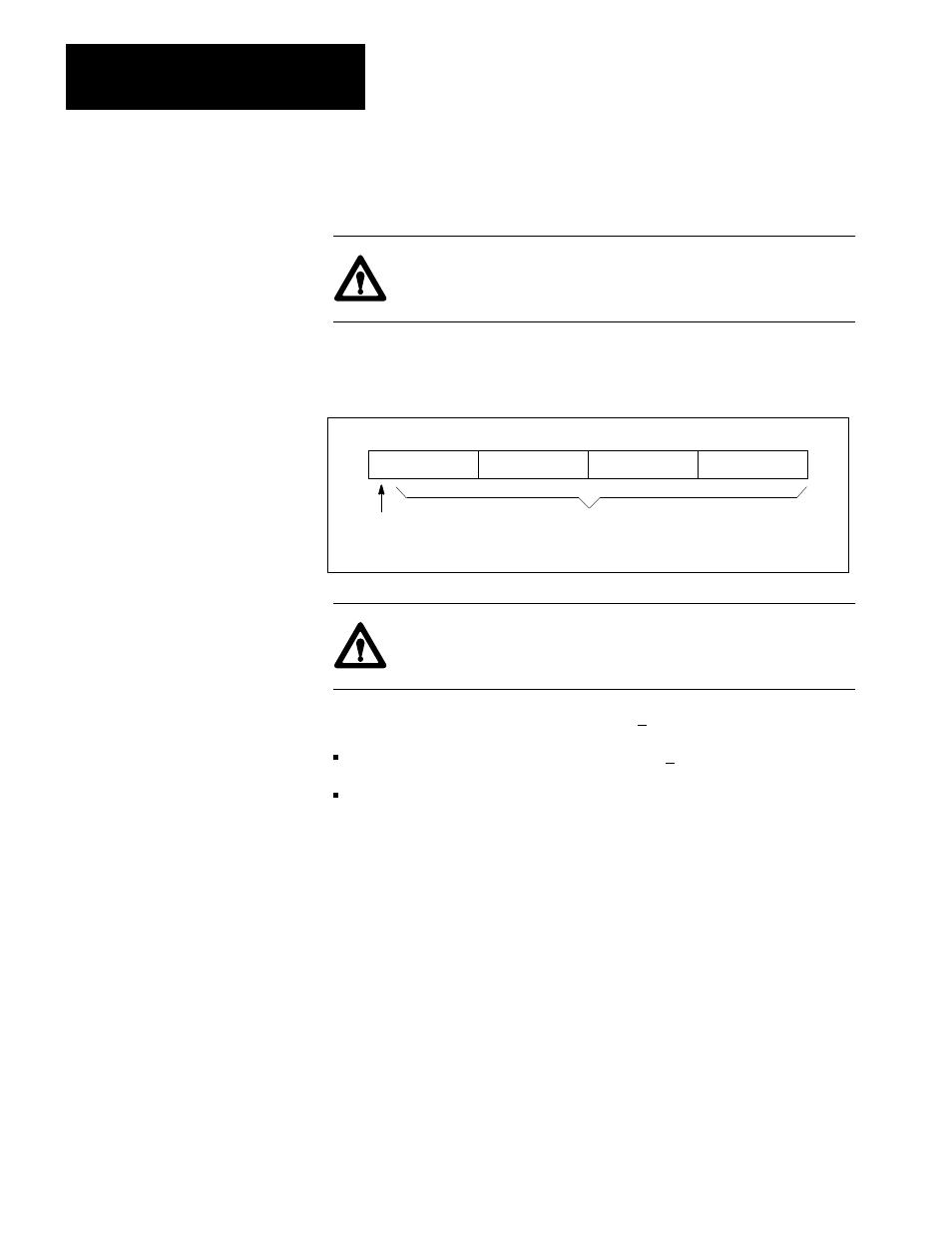
Figure 7.3
Analog Range Word
50058
Maximum analog range,
BCD or binary
1 - 100%
Sign:
0 = + Direct action
1 = - Reverse action
15 14 13 12 11 10 09 08 07 06 05 04 03 02 01 00
..
.
..
.
...
..
.
..
.
...
..
.
..
.
...
..
.
..
.
...
..
.
..
.
...
..
.
..
.
...
..
.
..
.
...
..
.
..
.
...
..
.
..
.
...
..
.
..
.
...
..
.
..
.
...
..
.
..
.
...
ATTENTION: Make sure that the analog output doesn’t exceed the
maximum for your device.
Example: To set an analog output range of +70 mA:
configure the analog output DIP switches for +100 mA
specify an analog range of 70% in the analog range word
Analog Calibration Constants (words 3, 4 and 32, 33)
The analog calibration constants specify the highest velocity that the axis can
attain in each direction. These rates, associated with the maximum positive and
negative analog outputs, are 327.67 ips (inches per second) or 3276.7 mmps
(millimeters per second) for binary format. For BCD the maximum is 99.99 ips
or 999.9 mmps.
The module uses these parameters to determine the relationship between the
analog output and the speed of the axis. A separate parameter for each direction
compensates for directional differences of the device (the zero-position offset
defines the positive and negative directions). The module performs this
compensation by adjusting the loop gains (proportional, integral, derivative, and
feedforward).