Initializing and tuning the axes chapter 8 – Rockwell Automation 1771-QB Linear Pos. User Manual
Page 121
Initializing and Tuning the Axes
Chapter 8
8Ć3
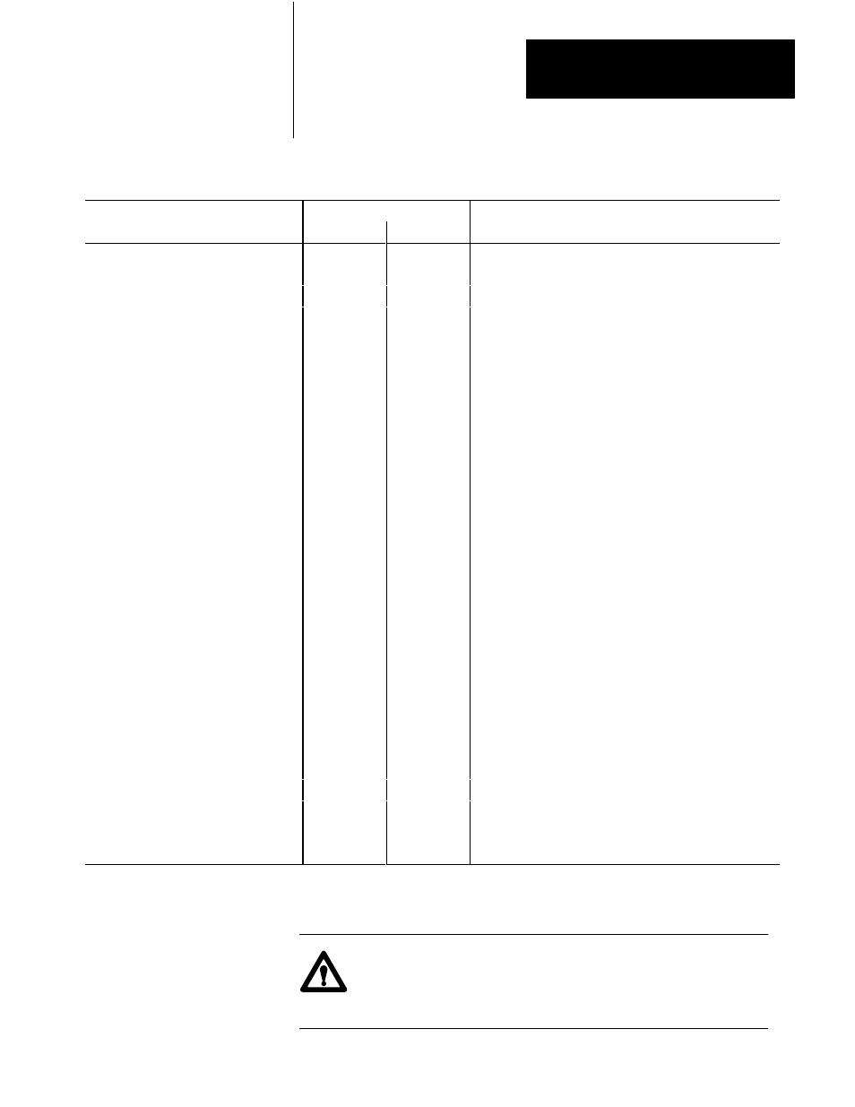
Table 8.A
Default Parameter Block Settings
Parameter
Suggested Values
Comments
Inches
Metric
Analog range
100
100
Check servo valve rating
+Analog calibration constant
2500
6350
Set to maximum velocity in positive direction
-Analog calibration constant
2500
6350
Set to maximum velocity in negative direction
(MS) Transducer calibration constant
9
3
Multiply this by the number of circulations
(LS) Transducer calibration constant
500
5600
Multiply this by the number of circulations
(MS) ZeroĆposition offset
Ć5
Ć12
Application dependent
(LS) ZeroĆposition offset
0
Ć700
Application dependent
+Software travel limit
210
533
Set in front of mechanical stop in (+) direction
-Software travel limit
Ć10
Ć25
Set in front of mechanical stop in (-) direction
InĆposition band
100
254
Optional Ć adjust for your application
PID band
500
1270
Rarely necessary to use a smaller value
Deadband
0
0
Rarely necessary or desirable
Excess following error
1000
2540
NonĆzero value important for safety
Maximum PID error
1000
2540
NonĆzero value important for safety
Integral term limit
10
10
Important to prevent integral windup
Proportional gain
600
600
Follow tuning procedure
Gain break speed
0
0
Rarely necessary
Gain factor
0
0
Rarely necessary
Integral gain
420
420
Set to 70% of proportional gain value
Derivative gain
420
420
Set to 70% of proportional gain value
Feedforward gain
300
300
Use these values or follow optional tuning procedure
Global velocity
1000
2540
Must be less than maximum velocity
Global acceleration
1000
2540
Application dependent
Global deceleration
1000
2540
Application dependent
Velocity smoothing constant
300
762
Application dependent
Low jog rate
100
254
Must not exceed high jog rate
High jog rate
1000
2540
Must be less than maximum velocity
Reserved
0
0
Reserved
0
0
Make sure that you have set the analog configuration switches correctly and that
you have entered the correct range into the parameter block.
ATTENTION: Incorrect analog output configuration can cause
sudden high-speed motion. Incorrect analog output polarity will
cause the axis to accelerate out of position when you close the loop.