Discrete outputs, Hardware description chapter 4 – Rockwell Automation 1771-QB Linear Pos. User Manual
Page 37
Hardware Description
Chapter 4
4Ć8
The analog output interface circuit is electrically isolated from the 1771 I/O
chassis. This feature protects other devices on the 1771 backplane from noise
and current surges in the analog output circuit. An internal relay automatically
shuts off these outputs in the event of a module fault. For details on connecting
the servo valve interface, see Chapter 5.
Important: Throughout this manual we refer to servo valves, but you can also
use the analog outputs to control proportional valves. All references to servo
valves also apply to proportional valves.
Terminals 36 through 39 on the module’s wiring arm provide connection points
for discrete output signals. Each axis has two discrete outputs: Output 1 which
can be configured to be either an in-position or programmable output, and
Output 2 which can be configured to be either a loop fault or programmable
output. (See Chapter 9.) The default configuration is in-position and loop fault.
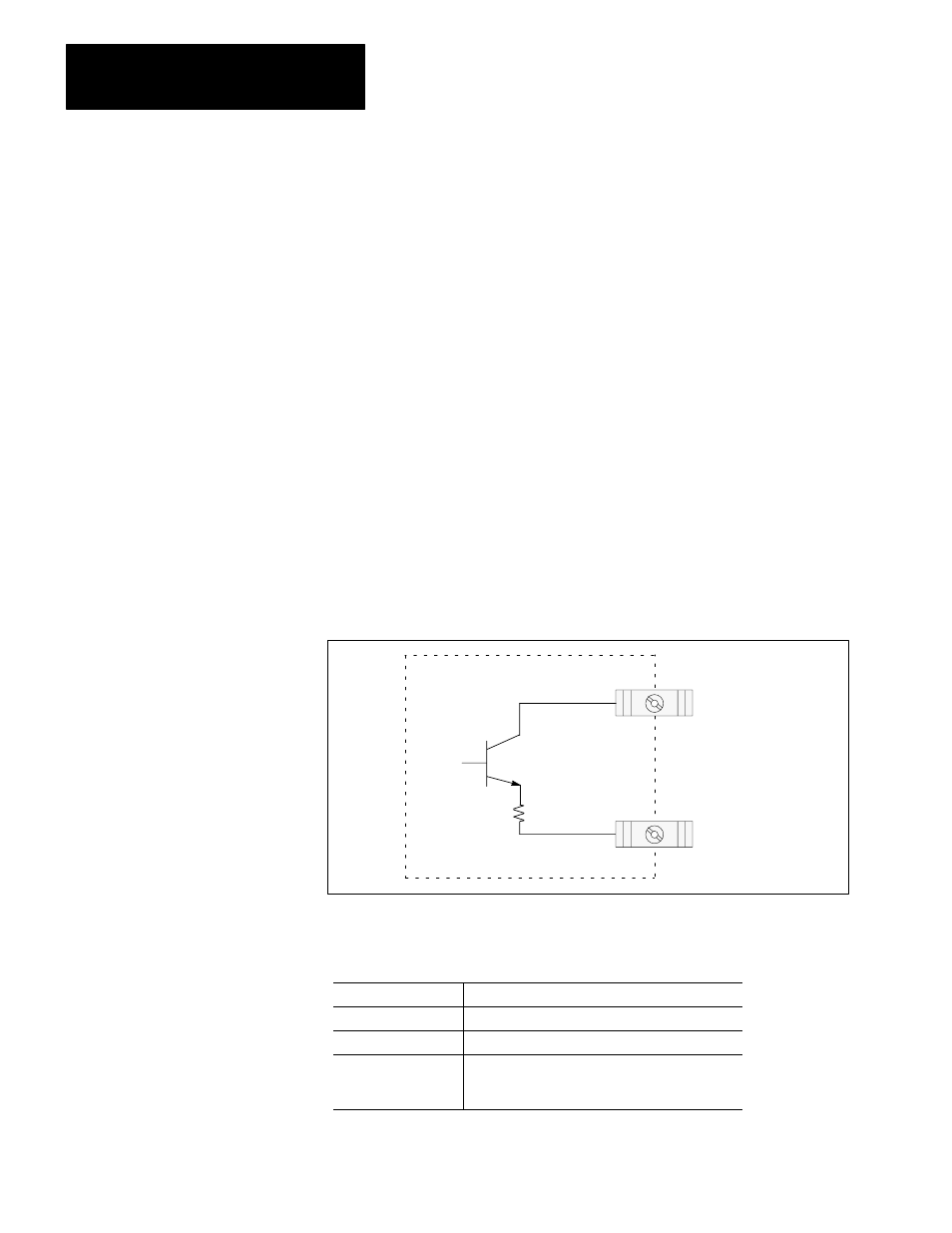
The discrete outputs are current sources. Figure 4.4 gives a simplified schematic
of a discrete output circuit.
Figure 4.4
Simplified Schematic of a Discrete Output
50042
1771 Ć QB MODULE
40
OUTPUT SUPPLY
3.9
37
OUTPUT 1
5
0
0
4
2
Here are the characteristics of the discrete outputs:
Low
no voltage applied to the output
High
output supply voltage applied to output
Maximum Current
100 mA
Voltage Drop
1.6 VDC maximum (at 100 mA) between the
discrete output power supply (terminal 40) and the
discrete outputs
Discrete Outputs