System overview – Rockwell Automation 1771-QB Linear Pos. User Manual
Page 15
Introducing the Linear Positioning Module
Chapter 1
1Ć4
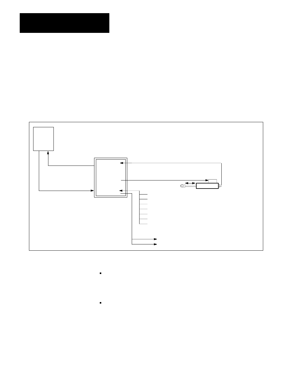
Figure 1.2 shows one of the module’s two control loops within a linear
positioning system for closed-loop axis control. The module communicates with
a programmable controller through the 1771 backplane.
The programmable logic controller sends commands and user-programmed data
from the data table to the module as directed by a block-transfer write
instruction.
Figure 1.2
System Overview
50033
PLC
Processor
Linear
Positioning
Module
D
Status Block
D
Parameter Block
D
Setpoint Block
D
Motion Block
D
Command Block
D
Jog Forward
D
Jog Reverse
D
Hardware Start
D
Auto/Manual
D
Hardware Stop
D
Input 1
D
Input 2
Linear Displacement
Transducer
D
Output 1
D
Output 2
Discrete Outputs
D
Discrete Inputs
Transducer
Analog Output
Servo Valve
PistonĆType
Cylinder
NOTE: All inputs and outputs are
duplicated for the second axis.
Interface
Using PLC programming, you can:
send configuration and control parameters to the module via parameter,
setpoint, motion, and command blocks. With this data the module determines
axis parameters, calculates velocity curves, and commands axis
end-positions. (See Chapters 7 and 9.)
read status blocks to monitor axis position and status indicators in your
process control system. (See Chapter 6.)
The module’s analog outputs (one for each control loop) connect to servo or
proportional valves via wiring arm terminals. The module controls speed and
position by adjusting the voltage or current levels of the analog outputs 500
times each second.
System Overview