Wiring arm terminals, Hardware description chapter 4 – Rockwell Automation 1771-QB Linear Pos. User Manual
Page 31
Hardware Description
Chapter 4
4Ć2
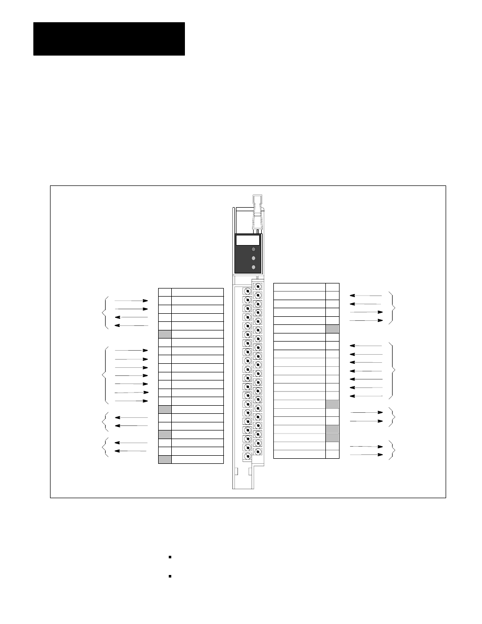
The module draws power for its internal circuitry and communicates with the
programmable controller through the 1771 universal I/O chassis. You make all
other connections through the wiring arm terminals. Cable length can be up to
200 feet for these connections, depending on the gauge used. See Chapter 5 for
wiring guidelines. Figure 4.2 shows the wiring arm terminals for both control
loops.
Figure 4.2
Wiring Arm Terminals
Transducer
Interface
50010
LINEAR
POSITIONING
FAULT
LOOP1
ACTIVE
LOOP2
ACTIVE
LOOP 2
+ GATE
- GATE
+ INTERR
- INTERR
+5 COMMON
UNUSED
AUTO/MAN
START
STOP
JOG FWD
JOG REV
INPUT 1
INPUT 2
I/P COMMON
+ ANALOG
- ANALOG
±
15 COMMON
OUTPUT 1
OUTPUT 2
O/P SUPPLY
NO.
2
4
6
8
10
12
14
16
18
20
22
24
26
28
30
32
34
36
38
40
LOOP 1
+ GATE
- GATE
+ INTERR
- INTERR
+5 VDC
UNUSED
AUTO/MAN
START
STOP
JOG FWD
JOG REV
INPUT 1
INPUT 2
I/P SUPPLY
+ ANALOG
- ANALOG
+ 15 VDC
- 15 VDC
OUTPUT 1
OUTPUT 2
NO.
1
3
5
7
9
11
13
15
17
19
21
23
25
27
29
31
33
35
37
39
Discrete
Inputs
Analog
Outputs
Discrete
Outputs
Transducer
Interface
Discrete
Inputs
Analog
Outputs
Discrete
Outputs
The input and output terminals of each of the module’s control loops are in four
groups. Each group is electrically isolated from the 1771 backplane and from
the three other groups:
transducer interface terminals
discrete input terminals
Wiring Arm Terminals