Chapter summary – Rockwell Automation 1772-LS_LSP,D17726.8.6 PROG/OPER MANUAL-MINI PLC-2/05 User Manual
Page 52
Scan Theory
Chapter 5
5Ć5
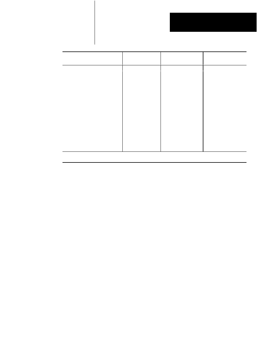
Instruction Name
Instruction
False
Instruction
True
Symbol
Label
LBL
34
Ć
Return Ć(RET)Ć
30
15
Jump to subroutine Ć(JSR)Ć
100
15
Jump Ć(JMP)Ć
55
15
Block transfer read BLOCK
XĆFER 1
80
75
Block transfer write BLOCK
XĆFER 0
80
75
Sequencer load SEQ 2
390(80/extra word)
105
Sequencer input SEQ 1
420(90/extra word)
55
Sequencer output SEQ 0
470(90/extra word)
110
FileĆtoĆword move FILE 12
250
45
WordĆtoĆfile move FILE 11
250
45
FileĆtoĆfile move FILE 10440 (+10/word
transferred)
200
1
When a rung that contains a ZCL instruction is false, the execution time of each instruction between the start fence and
end fence is 17 microseconds per word.
Here is an explanation of the rungs in Figure 5.2:
Rung 1 - The count increments its accumulated value each time this rung
is true.
Rung 2 - This rung enables the counter to increment on the next scan. If we did
not have this rung, the counter would always be true and it would not
increment. Remember: Counters increment only on false to true transitions.
Rung 3 - The timer times in tenths of seconds when we are counting. This
value is displayed on the industrial terminal screen.
Rung 4 - The average scan time is displayed beneath store 2 and store 3
in milliseconds.
Important: Refer to three digit math in chapter 10.
Rung 5 - The counter overflow bit is re-setting the timer.
Rung 6 - The counter overflow bit is resetting the counter.
We described scan sequence and a method to measure average scan time. The
next chapter explains some of the instructions you use in a program.
Chapter Summary