Rockwell Automation 1772-LS_LSP,D17726.8.6 PROG/OPER MANUAL-MINI PLC-2/05 User Manual
Page 158
Block Transfer
Chapter 14
14-3
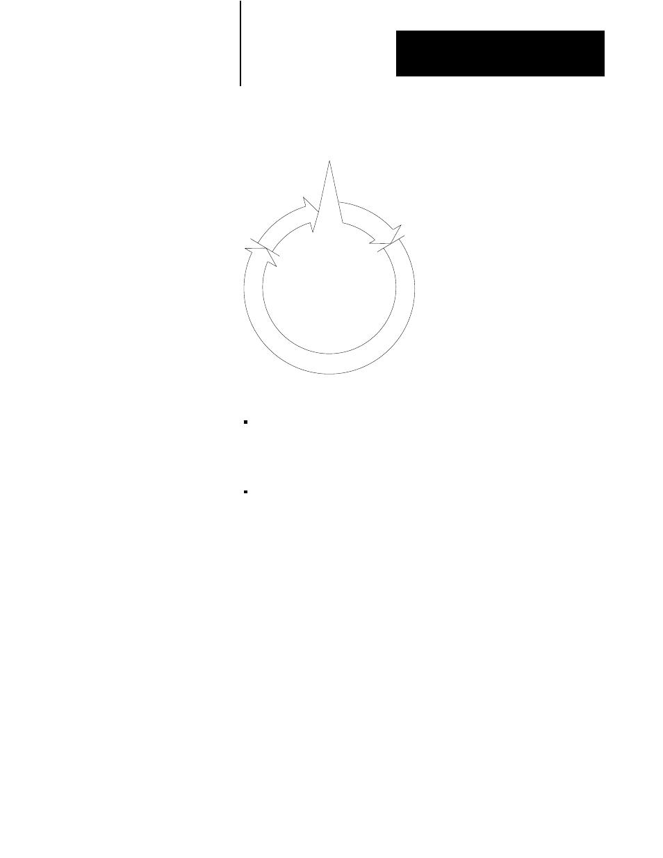
Figure 14.2
Block Transfer Diagram
Transfer is made in I/O Scan
Output
Scan
Input
Scan
Request is made in Program Scan
10377ĆI
Program scan - When the rung goes true, the instruction is enabled. The
number of words to be transferred and the read or write bit that controls
the direction of transfer are set by a bit pattern in the output image
table byte.
I/O scan - The processor requests a transfer by sending the output image
table byte data to the block transfer module during the scan of the output
image table. The module signals that it is ready to transfer. The
processor then interrupts the I/O scan and scans the timer/counter
accumulated area of the data table, looking for the address of the
module that is ready to transfer. The module address is stored in BCD
at a word address in the same manner as an accumulated value of a
timer is stored. The module address was entered by the programmer
when entering the block instruction parameters. The word address at
which the module address is stored is called the data address of
the instruction.
Once the module address is found, the processor locates the address of the
file to which (or from which) the data is transferred. The file address is
stored in BCD at an address 100 above the address containing the module
address. This is done in the same manner that the processor locates the
preset value of a timer in a word address 100 above the accumulated value
address. The analogy between block transfer and timer/counter data and
addresses is shown in Table 14.A.