Rockwell Automation 1772-LS_LSP,D17726.8.6 PROG/OPER MANUAL-MINI PLC-2/05 User Manual
Page 271
Quick Reference
Appendix C
CĆ15
Table C.N
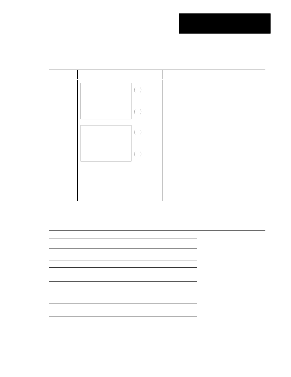
Block Transfer Instructions
Key Sequence
1770-T3 Display
Instruction Notes
BLOCK XFER
0
EN
Block Xfer Write
Data Addr:
Module Addr:
Block Length:
File:
100
001
110Ć 110
DN
030
010
06
110
06
Output instruction.
Block length depends on kind of module.
Entire file transferred in one scan.
Done bit remains on for one scan after valid transfer.
BLOCK XFER
1
EN
Block Xfer Write
Data Addr:
Module Addr:
Block Length:
File:
100
001
110Ć 110
DN
030
010
06
110
06
Data read from I/O module must be buffered.
Uses two words of user program for each instruction
BLOCK XFER
0
BLOCK XFER
1
Enter both instruction blocks for bidirectional
block transfer.
Set block lengths equal or to default value for module.
Same module address used for read and write instruction.
Enable read and write instructions in same scan.
Order of operation determined by the module.
See the module user's manual.
NOTE: Numbers shown are default values. Numbers in shaded areas must be replaced by user-entered values. The number of
default address digits initially displayed (3 or 4) will depend on the size of the data table.
To access the Data Monitor Display, enter all instruction parameters. Press key sequence:
[DISPLAY][0] for the binary monitor mode;
[DISPLAY][1] for the hexadecimal monitor mode.
This Value:
Stores the:
Data Address
First possible address in the timer/counter accumulated value area
of the data table
Module Address
RGS for R = rack, G = module, S = slot number
Block Length
Number of words to be transferred
(enter 00 for default value or for 64 words)
File
Address of the first word of the file
Enable bit Ć(EN)Ć
Automatically entered from the module address
Set on when the rung containing the instruction is true
Done bit Ć(DN)Ć
Automatically entered from the module address
Remains on for 1 program scan following successful transfer