Rockwell Automation 20-COMM-Q ControlNet Adapter User Manual
Page 71
Configuring the I/O
4-35
20-COMM-C/Q ControlNet Adapter User Manual
Publication 20COMM-UM003F-EN-P
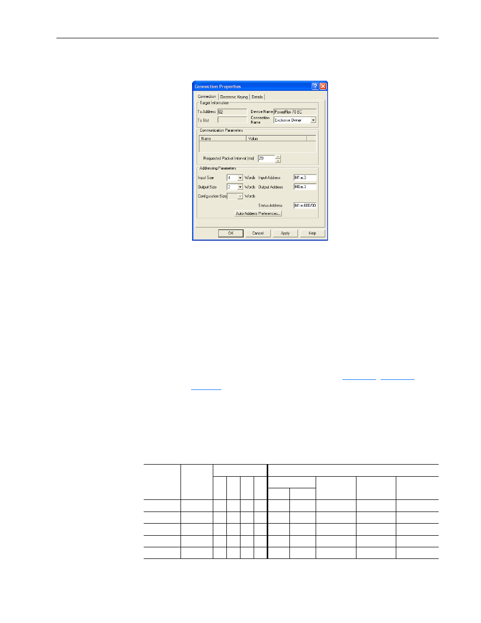
10. Right-click the PowerFlex 70 EC drive row in the screen and select
Insert Connection… to display the Connection Properties screen.
a. In this screen, leave the Connection Name box at the default value
shown.
b. For the Requested Packet Interval box, choose a value that is
suitable for your application, but is at least 5 ms.
c.
For the Input Size and Output Size boxes, use the pull-down menu
to choose the number of words that are required for your I/O.
The size will depend on the I/O that you enabled in the adapter
using Parameter 13 - [DPI I/O Cfg]. For this example, an Input
Size of ‘12’ and an Output Size of ‘10’ are selected.
Depending on the size of the drive’s Reference/Feedback and the number
of Datalinks used in your I/O configuration,
,
defines the number of 16-bit words that you need to enter for
the Input Size and Output Size boxes.
Table 4.G Drives with 16-bit Reference/Feedback and 16-bit Datalinks
These products include the following:
• PowerFlex 70 drives with standard or enhanced control
• SMC Flex smart motor controllers
• PowerFlex 700 drives with standard control
• SMC-50 smart motor controllers
• PowerFlex 700H drives
Logic
Command/
Status
Ref/Fdbk
(16-bit)
Datalinks (16-bit)
User Configured Settings
A
B
C
D
Size in Words
Par. 13 -
[DPI I/O Cfg]
Par. 25 -
[M-S Input]
Par. 26 -
[M-S Output]
Input
Output
✔
✔
4
2
…0 0001
…0 0001
…0 0001
✔
✔
✔
6
4
…0 0011
…0 0011
…0 0011
✔
✔
✔
✔
8
6
…0 0111
…0 0111
…0 0111
✔
✔
✔
✔
✔
10
8
…0 1111
…0 1111
…0 1111
✔
✔
✔
✔
✔
✔
12
10
…1 1111
…1 1111
…1 1111