Table 4.c – Rockwell Automation 20-COMM-Q ControlNet Adapter User Manual
Page 57
Configuring the I/O
4-21
20-COMM-C/Q ControlNet Adapter User Manual
Publication 20COMM-UM003F-EN-P
Table 4.C Drives with 32-bit Reference/Feedback and 32-bit Datalinks
These products include the following:
When using Datalinks, up to 8 drive [Data In xx] parameters (300…307)
and/or up to 8 [Data Out xx] parameters (310…317) must be assigned to
point to the appropriate drive parameters for your application.
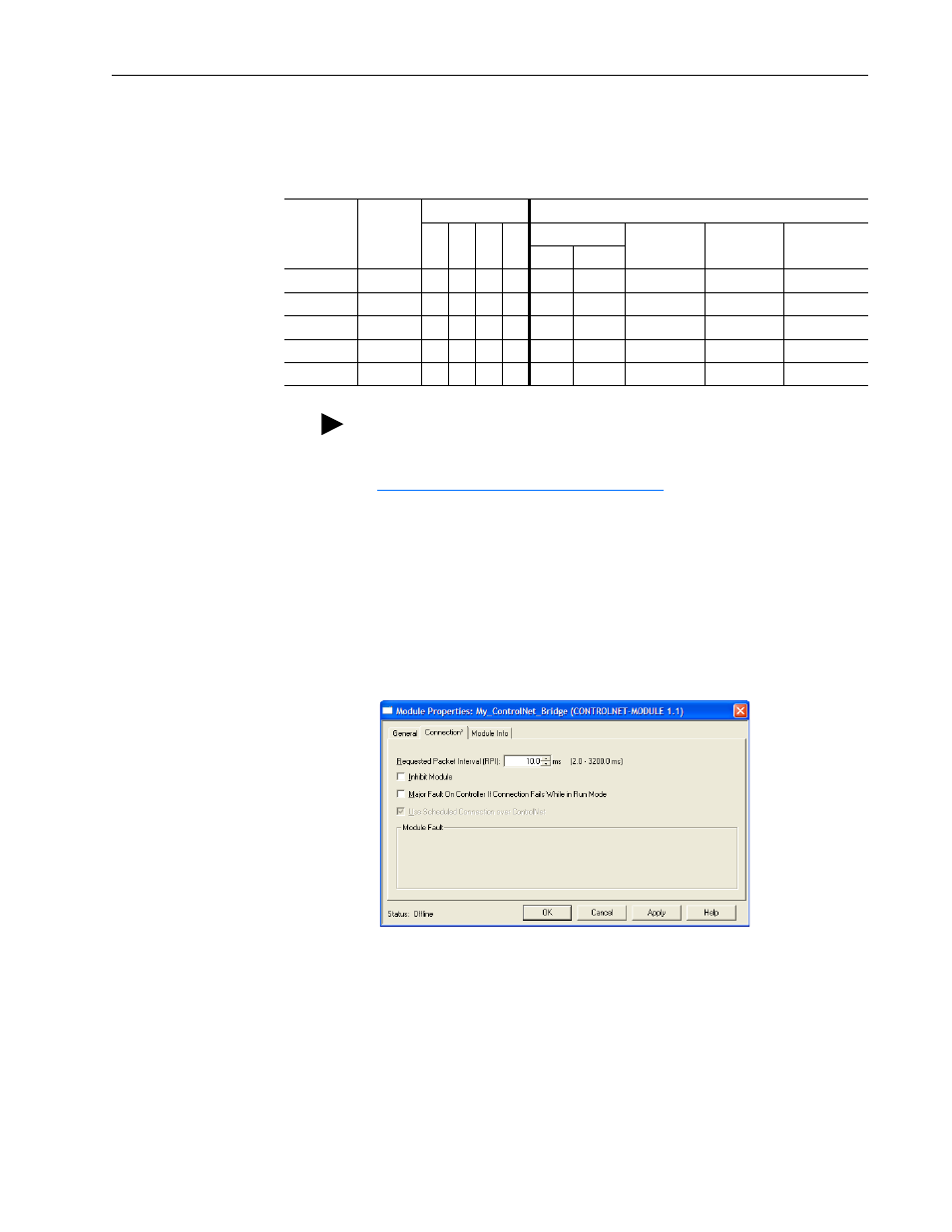
7. After setting the information in the drive’s New Module screen, click
OK.
The Module Properties screen appears.
8. Click the Connection tab.
9. In the ‘Requested Packet Interval (RPI)’ box, set the value to 5.0
milliseconds or greater.
This value determines the maximum interval that a controller should
use to move data to and from the adapter. To conserve bandwidth, use
higher values for communicating with low priority devices. For this
example, leave the ‘Inhibit Module’ and ‘Major Fault…’ boxes
unchecked.
10. Click OK.
• PowerFlex 700S drives with Phase I or Phase II control
• PowerFlex 753 drives
• PowerFlex 700L drives with 700S control
• PowerFlex 755 drives
Logic
Command/
Status
Ref/Fdbk
(32-bit)
Datalinks (32-bit)
User Configured Settings
A
B
C
D
Size in Words
Par. 13 -
[DPI I/O Cfg]
Par. 25 -
[M-S Input]
Par. 26 -
[M-S Output]
Input
Output
✔
✔
6
4
…0 0001
…0 0001
…0 0001
✔
✔
✔
10
8
…0 0011
…0 0011
…0 0011
✔
✔
✔
✔
14
12
…0 0111
…0 0111
…0 0111
✔
✔
✔
✔
✔
18
16
…0 1111
…0 1111
…0 1111
✔
✔
✔
✔
✔
✔
22
20
…1 1111
…1 1111
…1 1111
TIP: For instructions on configuring the I/O for the adapter using
Parameter 13 - [DPI I/O Cfg] and its Master-Slave hierarchy using
Parameters 25 - [M-S Input] and 26 - [M-S Output], see