Resetting the adapter, Viewing the adapter status using parameters – Rockwell Automation 20-COMM-Q ControlNet Adapter User Manual
Page 35
Configuring the Adapter
3-7
20-COMM-C/Q ControlNet Adapter User Manual
Publication 20COMM-UM003F-EN-P
Resetting the Adapter
Changes to switch settings and some adapter parameters require that you
reset the adapter before the new settings take effect. You can reset the
adapter by power cycling the drive or by using Parameter 09 - [Reset
Module].
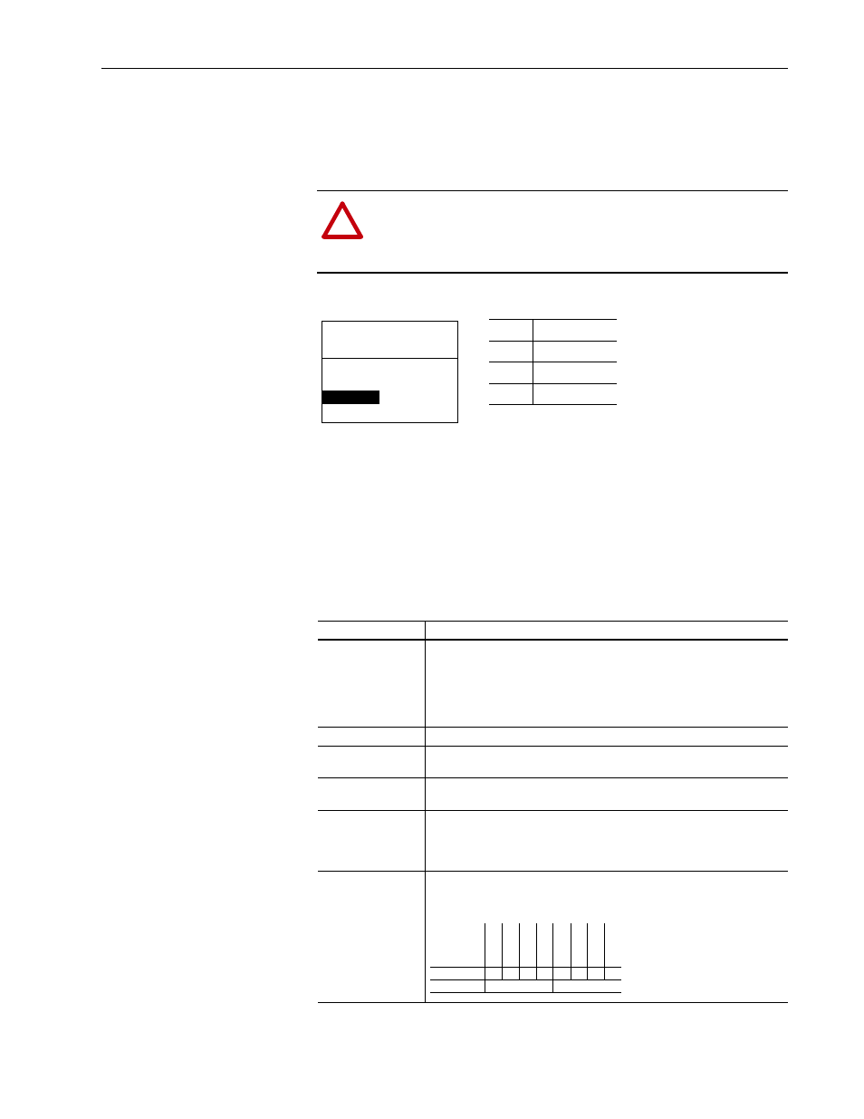
Set Parameter 09 - [Reset Module] to ‘1’ (Reset Module).
When you enter ‘1’ (Reset Module), the adapter will be immediately reset.
When you enter ‘2’ (Set Defaults), the adapter will set all adapter
parameters to their factory-default values. After performing a Set Defaults,
enter ‘1’ (Reset Module) so that the new values take effect. The value of this
parameter will be restored to ‘0’ (Ready) after the adapter is reset.
Viewing the Adapter Status
Using Parameters
The following parameters provide information about the status of the
adapter. You can view these parameters at any time.
!
ATTENTION: Risk of injury or equipment damage exists. If the
adapter is transmitting control I/O to the drive, the drive may fault
when you reset the adapter. Determine how your drive will
respond before resetting a connected adapter.
Value
Description
0
Ready (Default)
1
Reset Module
2
Set Defaults
Port 5 Device
20-COMM-C
Parameter #: 09
Reset Module
1
Reset Module
Parameter
Description
04 - [CN Addr Act]
The node address used by the adapter. This will be one of the following values:
• The address set by the rotary switches.
• The value of Parameter 03 - [CN Addr Cfg].
• An old address of the switches or parameter if they have been changed and
the adapter has not been reset.
06 - [CN Rate Act]
The data rate used by the adapter.
07 - [Ref/Fdbk Size] The size of the Reference/Feedback. It will either be 16 bits or 32 bits. It is set
in the drive and the adapter automatically uses the correct size.
08 - [Datalink Size]
The size of the Datalinks. It will either be 16 bits or 32 bits. It is set in the drive
and the adapter automatically uses the correct size.
12 - [CN Active Cfg] Source from which the adapter node address is taken. This will be either ‘0’
(Switches) or ‘1’ (EEPROM) in which the address from Parameter 03 - [CN
Addr Cfg] is stored. The source is determined by the settings of the adapter
Node Address switches.
14 - [DPI I/O Act]
The Reference/Feedback and Datalinks used by the adapter. This value is the
same as Parameter 13 - [DPI I/O Cfg] unless the parameter was changed
and the adapter was not reset.
Bit Definition
Not Used
Not Used
Not Used
Dat
alink D
Dat
alink C
Dat
alink B
Dat
alink A
Cmd/
Ref
Default
x
x
x
0
0
0
0
1
Bit
7
6
5
4
3
2
1
0
0 = I/O disabled
1 = I/O enabled