Rockwell Automation 20-COMM-Q ControlNet Adapter User Manual
Page 155
Using Explicit Messaging
6-27
20-COMM-C/Q ControlNet Adapter User Manual
Publication 20COMM-UM003F-EN-P
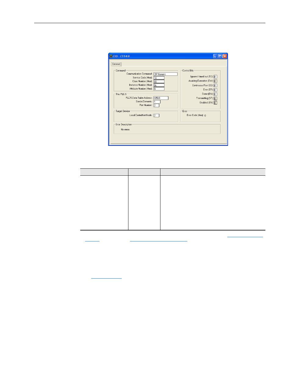
PLC-5 Controller – Formatting a Message to Write a Single Parameter
Figure 6.31 Write Single Message Configuration Screen
The following table identifies the data that is required in each box to
configure a message to write a single parameter.
General Tab
Example Value
Description
Communication Command
Service Code
Class Number
Instance Number
(1)
Attribute Number
(2)
PLC-5 Data Table Address
Size in Elements
Port Number
Local ControlNet Node
CIP Generic
10 (Hex.)
93 or 9F (Hex.)
(3)
8c (Hex.)
9 or A (Hex.)
N50:0
(4)
1
2
2
Command type for controller to write data to the drive.
Code for the requested service.
Class ID for the DPI Parameter Object.
Instance number is the same as parameter number.
Attribute number for the Parameter Value attribute.
An unused controller data table address containing the message
instruction. This address is the starting word of the source file.
Number of elements (words) to be transferred. Each element size
is a 16-bit integer.
Controller port to which the ControlNet network is connected.
The node address of the adapter connected to the drive.
(1)
The instance is the parameter number in the drive (Port 0). To write to a parameter in another port, see
Host DPI Parameter Object on page C-30
(Class code 0x9F) to determine the instance number.
For example, to write to parameter 51 of a peripheral in Port 5 of a PowerFlex 750-Series drive, the instance would be 21504 + 51 =
21555 or 5433 (Hex). In this example, Accel Time 1 is parameter 140 or 8C (Hex.).
(2)
Setting the Attribute value to ‘9’ will write the parameter value to the drive’s Nonvolatile Storage (EEPROM) memory, which retains
the parameter value even after the drive is power cycled. Important: When set to ‘9’, the EEPROM may quickly exceed its life cycle
and cause the drive to malfunction. Setting the Attribute value to ‘A’ will write the parameter value to temporary memory, which
deletes the parameter value after the drive is power cycled. When frequent write messages are required, we recommend using the
‘A’ setting.
(3)
See
Table 6.A on page 6-2
for limitations of PowerFlex 7-Class and PowerFlex 750-Series drives when using DPI Parameter Object
Class code 0x93 or Host DPI Parameter Object Class code 0x9F for explicit messaging.
(4)
In this example, Accel Time 1 is a 16-bit integer parameter requiring the Size in Elements field to be set to ‘1’. If the parameter being
written to is a 32-bit integer, the Size in Elements must be set to ‘2’. When using a PowerFlex 700S or PowerFlex 750-Series drive,
Accel Time 1 is a REAL (floating point) parameter. You must still write this data to an integer file with Size in Elements set to ‘2’. The
following page shows ladder logic to convert floating point data into integer files.