Rockwell Automation 20-COMM-Q ControlNet Adapter User Manual
Page 40
4-4
Configuring the I/O
20-COMM-C/Q ControlNet Adapter User Manual
Publication 20COMM-UM003F-EN-P
In this example, we use a 1756-CNB ControlNet Bridge (Series E), so
the 1756-CNB option is selected.
5. Click CREATE.
6. In the Select Major Revision pop-up dialog box, select the major
revision of its firmware.
7. Click OK.
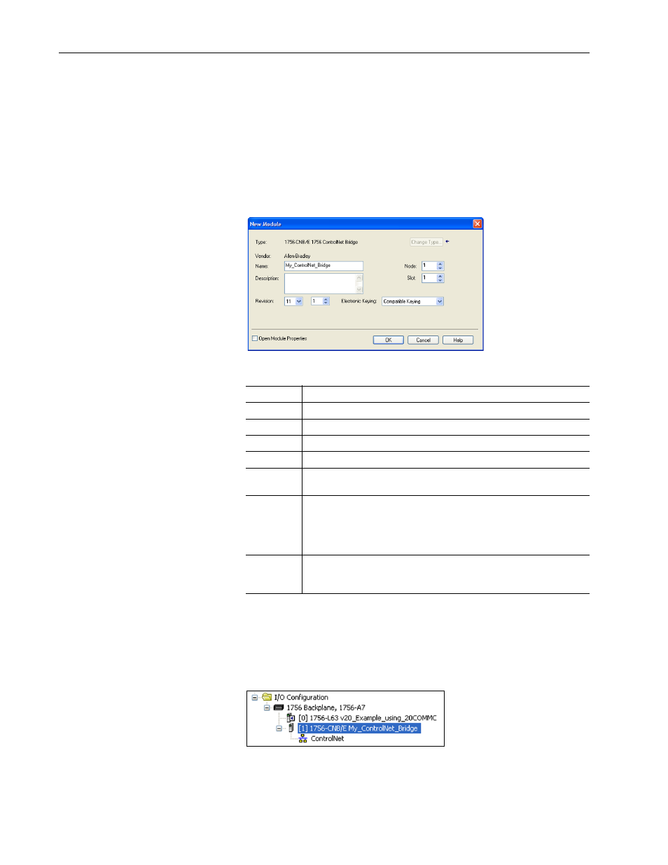
The bridge’s New Module screen appears.
8. Edit the following:
9. Click OK.
The bridge is now configured for the ControlNet network and added to
the RSLogix 5000 project. It appears in the I/O Configuration folder. In
our example, a 1756-CNB/E bridge appears under the I/O
Configuration folder with its assigned name.
For convenience, keep the project open. Later in this chapter the project
will need to be downloaded to the controller.
Box
Setting
Name
A name to identify the ControlNet bridge.
Description
Optional – description of the ControlNet bridge.
Node
The node address of the ControlNet bridge.
Slot
The slot of the ControlNet bridge in the rack.
Revision
The minor revision of the firmware in the bridge. (You already set the major
revision by selecting the bridge series in step 4.)
Electronic
Keying
Compatible Keying. The ‘Compatible Keying’ setting for Electronic Keying
ensures the physical module is consistent with the software configuration
before the controller and bridge make a connection. Therefore, be sure that
you have set the correct revision in this screen. See the online Help for
additional information on this and other Electronic Keying settings.
Open
Module
Properties
When this box is checked, clicking OK opens additional module properties
screens to further configure the bridge. When unchecked, clicking OK closes
the bridge’s New Module screen. For this example, uncheck this box.