Figure 14: installing the exhaust line – RKI Instruments SDM-2012 PC Controlled Configuration User Manual
Page 19
Hardware Setup • 14
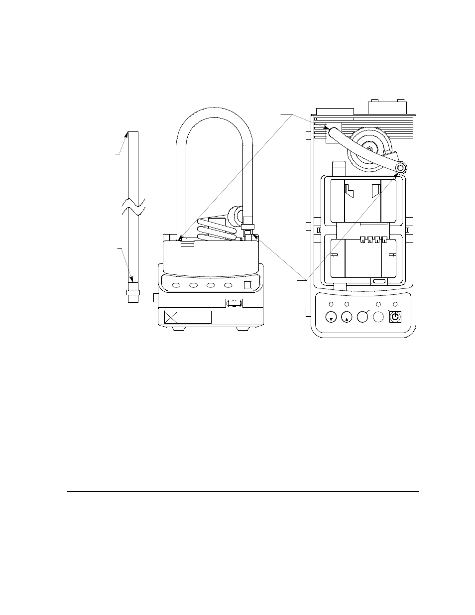
fitting, by pushing the open end of the exhaust tube onto the exhaust line
connection fitting located in the upper left corner of the instrument panel. You
may then push the black push on fitting of the exhaust line onto the exhaust
line storage fitting on the other side of the instrument panel.
6.
Install the air filter to the AIR fitting of each SDM-2012 so that the arrow on the
filter that indicates direction of flow is pointing towards the AIR fitting. Push the
open end of the flexible tube that is on one end of the filter onto the AIR fitting
on the back of the SDM-2012.
7.
Install the 10 foot long 5/16 inch ID flexible tube that is included with each
SDM-2012 on the exhaust fitting of each SDM-2012. Route the tube to an area
where the exhaust can be safely dispersed, such as an open window. Exhaust
tubing from multiple units can be daisy chained together in a manifold for more
convenient operation. In this case, the check valves that are provided with the
docking stations need to be used. See "Assembling a Manifold for Multiple
SDM-2012 Units" below for instructions.
CAUTION:
The maximum recommended length for the exhaust tube is 10 feet. Do
not use more than 10 feet of tubing or tubing with an ID of less than
5/16 inch for the exhaust tube or the bump test and calibration
accuracy will be adversely affected. The exhaust tube that is shipped
with the SDM-2012 has an ID of 5/16 inch and is 10 feet long.
Open End
BUMP
GX-2012 OFF
COPY
1SEC ON
3SEC OFF
SDM-2012
POWER
CAL.
EDIT
ENTER
CHARGE
SDM-2012
RKI
Instruments, Inc.
www.rkiinstruments.com
Black Push On Fitting
Step 2:
Black Push
On Fitting
Step 1:
Open End
Figure 14: Installing the Exhaust Line