Sdm-2012, Control panel – RKI Instruments SDM-2012 PC Controlled Configuration User Manual
Page 16
11 • Description
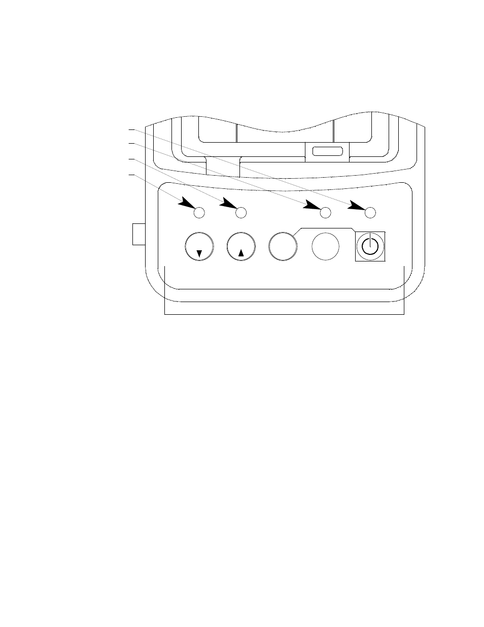
Control Panel
The control panel is used to setup and operate the docking station in the Standalone
configuration. It is located at the front of the docking station. It includes the control
buttons, the control button LEDs, and the CHARGE status LED.
Five control buttons are located on the control panel. From left to right they are BUMP
T
, CAL
S
, EDIT ENTER, COPY, and POWER. The BUMP
T
, CAL
S
, EDIT
ENTER, and COPY control buttons are not used in the PC Controlled configuration of
the SDM-2012. The BUMP
T
LED and CAL
S
LEDs indicate the results of bump
tests and calibrations, respectively. The COPY LED does not indicate anything in the
PC Controlled configuration but will be on if the SDM-2012 was used in the
Standalone configuration and calibration and bump test records are still stored in the
SDM-2012’s memory. The CHARGE LED is located above the POWER button and
functions as a pilot LED, a system failure LED, and a charge indication LED.
The POWER button turns the SDM-2012 on and off.
COPY
1SEC ON
3SEC OFF
CHARGE
POWER
GX-2012 OFF
BUMP
SDM-2012
CAL.
Control Buttons
EDIT
ENTER
BUMP LED
CHARGE LED
COPY LED
CAL LED
Figure 11: Control Panel